The Physics of the Return Path: Why Grounding Matters
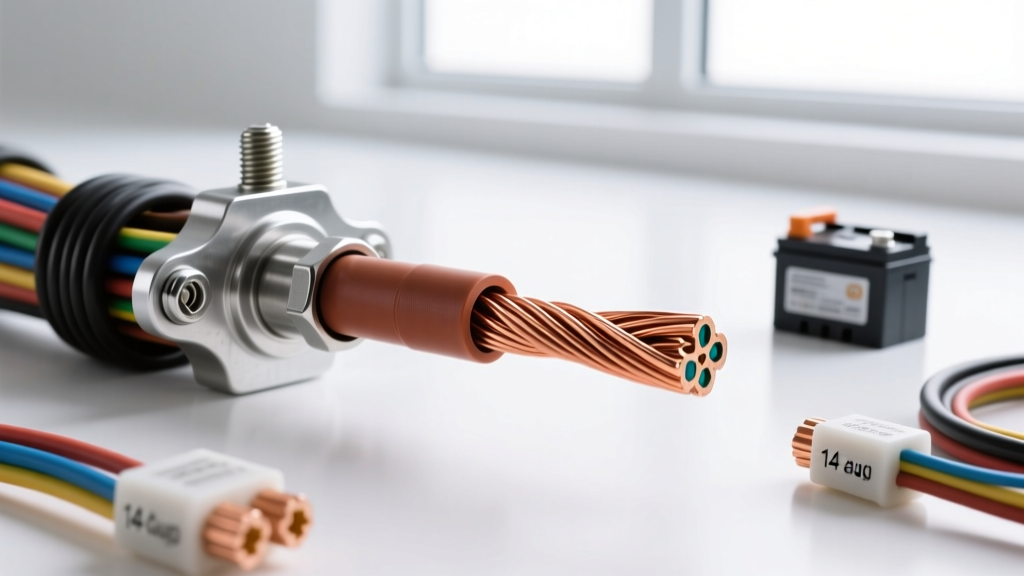
Beginners often view the ground wire as merely a physical anchor or an afterthought in automotive wiring. In reality, the ground wire is the critical return path that completes the circuit back to the negative terminal of the battery. Without a clean, low-resistance return path, even the highest-quality power wires will fail to deliver consistent voltage to sensitive electronics. When working with a 14 gauge ground wire, understanding the physics of voltage drop is essential for reliable vehicle operation.
According to Ohm's Law (V = I x R), voltage drop is determined by the current draw multiplied by the resistance of the wire. A standard 14 AWG copper wire has a DC resistance of approximately 2.525 ohms per 1,000 feet. If you are grounding a fuel pump relay that draws 10 amps, and the ground wire is 5 feet long (making the total circuit length 10 feet out and back), the resistance is roughly 0.025 ohms. This results in a voltage drop of 0.25V. While this is acceptable for most 12V chassis components, sensitive ECU sensors require an even tighter tolerance, which is why keeping 14 gauge ground wire runs as short as possible is a fundamental rule of automotive electrical design.
Where to Use (and NOT Use) 14 AWG Ground Wire
Using the correct wire gauge for the specific amperage load prevents overheating, voltage starvation, and potential electrical fires. The SAE J1128 Low Tension Primary Cable Standard outlines the thermal and electrical limits for automotive wiring. Based on these standards and real-world chassis routing, here is where 14 AWG excels and where it fails.
Ideal Applications for 14 Gauge Grounds
- Relay Coil Grounds: Pins 85 and 86 on standard ISO mini-relays typically draw less than 200mA. A 14 AWG wire is more than sufficient and provides excellent physical durability.
- ECU Sensor Returns: Throttle Position Sensors (TPS), Manifold Absolute Pressure (MAP) sensors, and coolant temperature sensors draw minimal current but require ultra-stable ground references to prevent erratic fuel trims.
- Low-Draw Lighting: LED marker lights, license plate lamps, and interior dome light circuits.
- Fuel Injector Grounds: High-impedance injectors draw between 1 to 4 amps, making 14 AWG the perfect OEM-equivalent choice.
Never Use 14 AWG For:
- Main Battery to Chassis Grounds: These must handle the full cranking amperage of the starter (often 200A+). Use 1/0 or 2/0 AWG.
- Alternator to Engine Block Grounds: Alternator output grounds require heavy-duty cabling (typically 4 AWG or 2 AWG) to prevent diode failure.
- High-Current Amplifiers or Winches: Audio amplifiers and electric winches demand dedicated high-gauge power and ground cables directly to the battery.
Technical Specifications & SAE Standards
When sourcing wire, always look for cross-linked polyethylene (XLPE) insulation, commonly designated as GXL, TXL, or SXL. These insulation types offer superior heat resistance and abrasion protection compared to standard PVC wire found in hardware stores. Below are the exact specifications for a high-quality automotive 14 AWG ground wire.
| Specification | 14 AWG Automotive Wire (GXL/TXL) |
|---|---|
| Cross-Sectional Area | 2.08 mm² |
| Stranding Configuration | 19 strands of 0.37mm bare copper |
| Nominal Insulation O.D. | 0.095 inches (GXL) / 0.085 inches (TXL) |
| DC Resistance (at 20°C) | 2.52 Ω / 1,000 ft |
| Max Continuous Ampacity | 15 Amps (Chassis Wiring, single conductor) |
| Temperature Rating | 125°C (GXL) / 150°C (SXL) |
Step-by-Step: Prepping and Crimping Your Ground Termination
A ground wire is only as good as its termination. Soldering is generally discouraged in high-vibration automotive environments because solder wicks into the wire strands, creating a stiff, brittle point that will eventually snap under engine harmonics. Instead, use high-quality ratcheting crimpers and adhesive-lined heat shrink terminals. For detailed visual guides on crimping techniques, refer to Haynes Automotive Wiring Tutorials.
- Strip the Insulation: Use a precision wire stripper set exactly to 14 AWG. Remove exactly 5/16" of insulation. Do not nick the copper strands, as this reduces the cross-sectional area and creates a weak point.
- Select the Terminal: For most automotive chassis grounds utilizing M5 or M6 bolts, select a #10 ring terminal (which has a 3/16" inner diameter stud hole). Ensure the terminal barrel is sized for 16-14 AWG (usually color-coded blue).
- The Crimp: Insert the wire into the barrel until the strands are flush with the insulation support crimp. Use a ratcheting crimper designed for insulated terminals. Squeeze until the ratchet releases. The wire grip and the conductor grip should both be tightly deformed around the wire.
- The Tug Test: Pull firmly on the wire. A properly crimped 14 AWG terminal will withstand over 40 lbs of pull force before failing.
- Heat Shrink: Apply heat evenly with a heat gun until the adhesive lining melts and oozes slightly from the edges, creating a waterproof seal against corrosion.
Chassis Prep: The Secret to a Perfect Ground Point
The most common beginner mistake is attaching a ground ring terminal to painted sheet metal or a rusty engine block. Paint, powder coat, and rust are electrical insulators. A poor chassis connection will introduce variable resistance, leading to flickering lights, erratic gauge readings, and ghost electrical codes.
The Proper Grounding Sequence
- Locate a Structural Point: Choose a thick, structural piece of metal. Avoid thin sheet metal brackets that can flex and crack the ground connection.
- Remove Paint and Rust: Use a 3M Scotch-Brite wheel or 80-grit sandpaper on a die grinder to strip away all paint, primer, and rust down to bare, shiny metal. The contact area should be slightly larger than the ring terminal.
- Hardware Selection: Use an external tooth lock washer (star washer) between the ring terminal and the bare metal. The teeth will bite into the copper and the steel, ensuring a gas-tight electrical connection that resists vibration.
- Fastener Torque: If using an M6x1.0 flange bolt, torque it to the manufacturer's specification, typically between 9 Nm and 12 Nm. Over-torquing can strip the threads in aluminum engine blocks.
- Corrosion Protection: Once torqued, spray the area with a zinc-rich cold galvanizing compound or coat the terminal in dielectric grease to prevent galvanic corrosion between the copper terminal and steel chassis.
Common Beginner Mistakes & Troubleshooting Matrix
Even with the correct 14 gauge ground wire, routing and circuit design errors can cause system failures. The Painless Performance Technical Tips database frequently highlights the dangers of 'daisy-chaining' grounds. Below is a troubleshooting matrix for common grounding issues.
| Symptom | Probable Cause | The Fix |
|---|---|---|
| ECU throws erratic sensor codes (e.g., P0121 TPS Performance) | Sensor ground is shared with a high-draw component like a cooling fan relay, causing voltage spikes on the return path. | Run a dedicated 14 AWG ground wire directly from the sensor back to the ECU ground bus or a clean, isolated engine block stud. |
| LED lights flicker at idle but stabilize at higher RPMs | The ground point is on a painted surface or uses a standard flat washer instead of a star washer, causing high resistance. | Remove the bolt, sand to bare metal, install an external tooth star washer, and re-torque. |
| Wire insulation melts near the terminal | Circuit is pulling more than 15A continuously, or the crimp was loose, creating localized resistance and heat. | Verify amperage draw. If over 15A, upgrade to 12 AWG wire. If draw is correct, cut off the terminal and re-crimp with a ratcheting tool. |
| Alternator whine heard through the audio system | Ground loop created by grounding audio components to a different chassis point than the head unit, utilizing thin wire. | Ensure all audio components share a single, massive ground point. 14 AWG is too small for amplifier grounds; upgrade to 4 AWG. |
Final Thoughts on Color Coding and Routing
While black is the universal standard for ground wires in aftermarket harnesses, OEM manufacturers often use variations. For example, Ford frequently uses a Black wire with a White stripe (BLK/WHT) for dedicated Powertrain Control Module (PCM) sensor grounds, while GM often utilizes solid Black for chassis grounds and Black/White for module grounds. When repairing or extending an OEM harness with your 14 gauge ground wire, always consult the vehicle-specific wiring diagram to maintain color-code consistency. Route your ground wires away from high-heat sources like exhaust manifolds and secure them every 12 to 18 inches using UV-resistant nylon zip ties or Adel clamps to prevent chafing against sharp metal edges.