Introduction to DeWalt 20V MAX Architecture in Automotive Applications
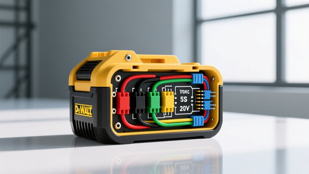
Repurposing high-capacity power tool batteries for automotive auxiliary systems has become a standard practice among overlanders, mobile ham radio operators, and off-grid technicians. The DeWalt 20V MAX platform, built on a 5-series (5S) Lithium-Ion NMC (Nickel Manganese Cobalt) architecture, offers exceptional energy density and high-discharge capabilities. However, integrating a DeWalt 20 volt battery wiring diagram into a 12V automotive power distribution block requires a precise understanding of the pack's internal Battery Management System (BMS), physical pinout configuration, and voltage sag under inductive loads.
Unlike standard 12V lead-acid or LiFePO4 automotive batteries, a DeWalt 20V pack operates at a nominal 18V and peaks at 21.0V. Connecting automotive accessories directly to these terminals will destroy 12V ECUs, LED light bar drivers, and portable fridge compressors. This technical reference outlines the exact pinout, cell chemistry specifications, and the correct DC-DC buck conversion topology required to safely build a portable, high-current automotive fuse block powered by DeWalt XR and Powerstack batteries.
DeWalt 20 Volt Battery Wiring Diagram & Connector Pinout
The physical interface of the DeWalt 20V MAX sliding battery pack features multiple contacts designed for tool communication, thermal monitoring, and high-current discharge. When fabricating a custom battery sled or using a pogo-pin block for auxiliary power, you must isolate the primary discharge pins while respecting the BMS safety interlocks.
| Pin Number | Function | Wire Color Code (Standard) | AWG / Specification | Description & BMS Logic |
|---|---|---|---|---|
| Pin 1 (Outer Left) | B+ (Positive) | Red | 10 AWG TXL or 8 AWG SGT | Main high-current positive discharge terminal. Connected directly to the BMS high-side MOSFETs and cell pack positive. |
| Pin 2 (Inner Left) | TH (Thermistor) | Yellow | 22 AWG | Temperature monitoring. The BMS reads resistance to prevent thermal runaway. Leave floating or bridge with a 10kΩ resistor if bypassing tool-side logic. |
| Pin 3 (Inner Right) | ID / Comm | White | 22 AWG | Pack identification and communication bus. Used by chargers and advanced tools to read cell balance and cycle count. |
| Pin 4 (Outer Right) | B- (Negative) | Black | 10 AWG TXL or 8 AWG SGT | Main high-current negative discharge terminal. Ground reference for the pack and BMS current shunt. |
Note: For pure power extraction, only Pin 1 (B+) and Pin 4 (B-) are required. Attempting to bypass the internal BMS by spot-welding directly to the 5S cell tabs is highly discouraged and violates SAE J2464 safety standards for lithium-ion abuse testing, as it removes over-current and short-circuit protection.
5S Li-Ion Discharge Curve & Automotive Buck Conversion
To integrate this 18V nominal system into a standard 12V/13.8V automotive ATC/ATO fuse block, a high-efficiency synchronous DC-DC buck converter is mandatory. Understanding the 5S discharge curve is critical for sizing the converter's input capacitors and setting the low-voltage cutoff (LVC) to prevent the DeWalt BMS from hard-locking the pack.
| State of Charge (SoC) | Pack Voltage (5S) | Per-Cell Voltage | Automotive System Status |
|---|---|---|---|
| 100% (Fully Charged) | 21.0V | 4.20V | Buck converter active; high thermal dissipation. |
| 75% | 19.8V | 3.96V | Optimal operating range for 300W step-down modules. |
| 50% (Nominal) | 18.0V - 18.5V | 3.60V - 3.70V | Peak efficiency point for synchronous buck topology. |
| 20% | 16.5V | 3.30V | Voltage sag under heavy load may trigger BMS cutoff. |
| 0% (BMS Cutoff) | 15.0V | 3.00V | BMS opens MOSFETs. Converter must cease drawing current before this threshold. |
According to data published by Battery University, drawing high amperage from Li-ion cells causes immediate voltage sag due to internal resistance (IR). If you pull 30A from a DeWalt 4.0Ah XR pack at 20% SoC, the voltage may momentarily sag below 15.0V, tripping the BMS under-voltage protection and shutting off your automotive accessories. To prevent this, configure your DC-DC buck converter's Low Voltage Disconnect (LVD) to 16.5V.
Automotive Integration: Building the Aux Distribution Harness
Building a reliable, high-current harness requires adherence to marine and automotive DC wiring standards, such as those outlined in ABYC E-11. Below is the step-by-step specification for wiring a DeWalt 20V battery sled to a 12V automotive fuse block.
Step 1: Connector and Sled Fabrication
Do not use alligator clips or temporary jumper wires. Use a CNC-machined or high-temp 3D-printed (ABS/Polycarbonate) battery sled equipped with copper-beryllium pogo pins or stamped brass contacts. Wire the B+ and B- terminals using 10 AWG TXL (Cross-linked polyethylene) wire, which is rated for under-hood automotive temperatures up to 125°C.
Step 2: High-Side Fusing and Disconnect
Install a 40A Class T or ANL fuse on the B+ (Red) wire within 4 inches of the battery sled contact. The DeWalt BMS is designed to trip during a dead short, but a physical fuse provides secondary protection against wiring harness fires. Following the fuse, integrate an Anderson Power Products SB50 quick-disconnect connector. This allows you to physically isolate the battery pack from the distribution block during vehicle storage or transport. Ensure the SB50 contacts are crimped using a Mil-Spec hex-crimp die and pulled to 40 lbs to verify retention.
Step 3: DC-DC Buck Converter Integration
Route the 10 AWG wires into a waterproof, potted synchronous buck converter (e.g., 300W, 20A continuous output). Set the output voltage precisely to 13.8V DC using a multimeter and the module's internal trim potentiometer. This 13.8V output mimics a running automotive alternator, ensuring compatibility with 12V fridges, ham radios, and LED light bars.
Step 4: Automotive Fuse Block Termination
Connect the 13.8V output of the buck converter to a marine-grade ATC/ATO fuse block (such as a Blue Sea Systems ST Blade). Use 10 AWG wire for the main feed into the fuse block's busbar. Individual circuits should be sized according to the accessory draw (e.g., 14 AWG for a 10A ham radio circuit, 12 AWG for a 15A portable air compressor circuit). All negative returns must be routed back to a dedicated negative busbar, which is then tied back to the B- pin on the DeWalt sled.
High-Current Draw & Thermal Management Troubleshooting
When powering automotive accessories like portable 12V air compressors or winch solenoid controllers, inductive startup spikes can exceed 40A for milliseconds. While the DeWalt BMS can handle brief peak loads, sustained high-current draws will trigger thermal throttling.
| Symptom | Technical Cause | Diagnostic & Corrective Action |
|---|---|---|
| Accessory shuts off after 3-5 minutes of heavy use. | BMS Thermal Cutoff. Internal NTC thermistors detect MOSFET heat exceeding 75°C. | Reduce continuous load. Upgrade to a DeWalt Powerstack pack, which utilizes pouch cells with lower internal resistance and superior thermal dissipation. |
| Buck converter emits high-pitch whine; output voltage fluctuates. | Input voltage sag causing the converter to hit its dropout threshold. | Measure voltage at the sled terminals under load. If sag exceeds 2.5V, upgrade wiring to 8 AWG SGT and verify crimp terminations for high resistance. |
| Battery pack "locks" and will not output power or accept a charge. | Deep discharge event. Cell voltage dropped below 2.5V, triggering permanent BMS fail-safe. | Place pack on a DeWalt fast charger. If the charger flashes red, the BMS has permanently opened the charge MOSFET. The pack must be recycled per EPA lithium-ion guidelines. |
Safety Protocols and Final Verification
Before deploying a DeWalt-powered automotive distribution block in the field, perform a load-bank test. Apply a 15A continuous resistive load to the 12V fuse block and monitor the input current on the 20V side. Due to buck converter efficiency (typically 92-95%), a 15A output at 13.8V (207W) will draw approximately 11.5A from the 18V battery pack. Verify that the 10 AWG TXL wiring remains at ambient temperature and that the Anderson SB50 connector shows no signs of thermal deformation. By strictly adhering to this DeWalt 20 volt battery wiring diagram and respecting the 5S BMS parameters, you can create a highly reliable, modular power supply for any automotive or off-grid application.