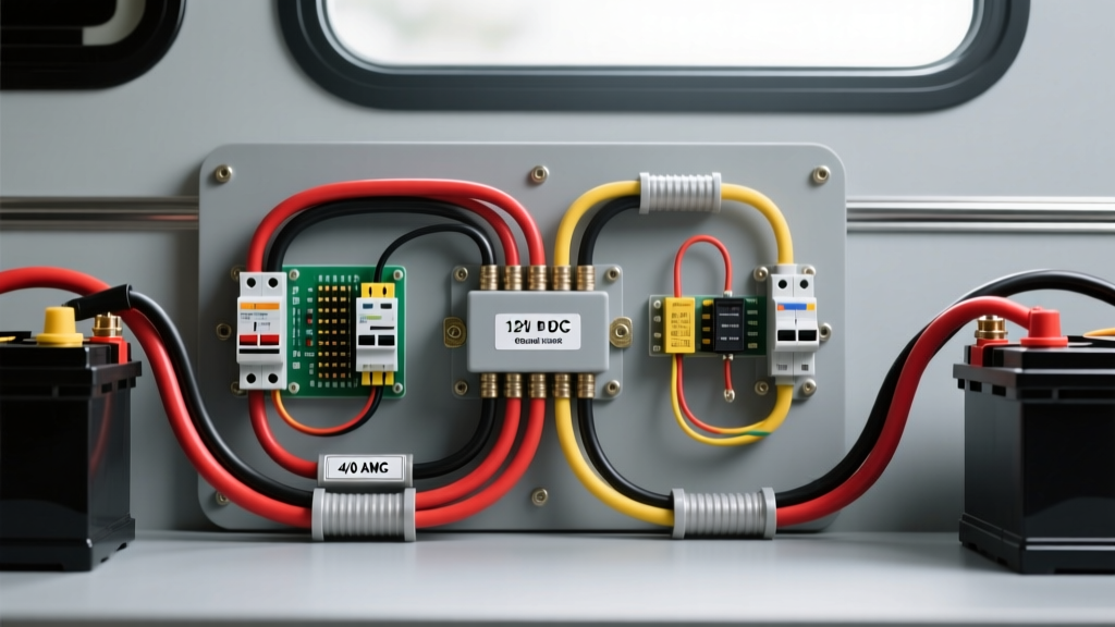
Architectural Overview of the RV 12V DC Power System
Designing and troubleshooting a reliable recreational vehicle electrical system requires a strict adherence to marine and automotive DC standards. Unlike standard passenger vehicles, an RV battery wiring diagram must manage two distinct DC domains: the chassis (starting) system and the house (deep-cycle or lithium) system. The house battery bank powers high-draw inverters, residential refrigerators, slide-out motors, and DC distribution panels. Failure to properly size conductors, route grounds, and isolate the battery banks results in severe voltage drop, thermal events, and premature battery degradation.
This technical specification reference outlines the exact AWG requirements, terminal torque specifications, overcurrent protection sizing, and diagnostic procedures for a Class A, Class C, or heavy-duty 5th wheel RV 12V DC architecture. All routing and sizing guidelines referenced herein align with SAE J1128 for low-tension primary cable and ABYC E-11 standards for DC electrical systems, which are widely adopted by premium RV manufacturers.
Primary RV Battery Wiring Diagram Specifications
The backbone of any RV house battery wiring diagram is the main positive trunk and the DC negative bus return path. For modern RVs equipped with 2000W to 3000W pure sine wave inverters, the main battery cables must handle sustained loads exceeding 250 amps. Utilizing undersized wiring or relying on chassis steel for the negative return path is a critical failure point.
DC Conductor Sizing and Voltage Drop Chart
The following table dictates the minimum American Wire Gauge (AWG) required for specific RV DC circuits, assuming a maximum allowable voltage drop of 3% (0.36V on a 12V nominal system) and an ambient temperature of 86°F (30°C). All wiring must be SGT (Special General Transport) or THHN/THWN stranded copper.
| AWG Size | Strand Count | Max Ampacity (Chassis) | Max Ampacity (Engine Bay/Bundled) | Typical RV Application | Voltage Drop per 10ft @ 100A |
|---|---|---|---|---|---|
| 4/0 AWG | 4234 | 260A | 195A | Main Inverter Positive/Negative, 300A+ Lithium Banks | 0.006V |
| 2/0 AWG | 2666 | 220A | 165A | House Battery Interconnects, 2000W Inverter Runs (<5ft) | 0.010V |
| 1/0 AWG | 2116 | 190A | 145A | 1500W Inverter Runs, Main DC Positive Trunk | 0.012V |
| 2 AWG | 1330 | 150A | 115A | Slide-out Motor Feeds, Leveling Jack Pumps | 0.020V |
| 4 AWG | 836 | 120A | 90A | DC-DC Chargers, Solar Charge Controller Trunks | 0.032V |
| 8 AWG | 524 | 80A | 60A | Fridge DC Heating Elements, High-Wattage Lighting Buses | 0.080V |
Note: For runs exceeding 15 feet, always upsize by one AWG tier to compensate for resistance accumulation. Utilize the Blue Sea Systems Circuit Wizard for precise run-length calculations.
House Battery Bank Configuration & Interconnects
When configuring a 400Ah to 800Ah house bank using 6V GC2 (Golf Cart) deep-cycle batteries, the series-parallel topology must be perfectly symmetrical to ensure equal charge and discharge distribution.
- Interconnect Cables: Use identical lengths of 2/0 AWG SGT cable for all series and parallel jumpers. A mismatched cable length as small as 6 inches introduces enough resistance to cause one battery string to over-discharge, leading to sulfation and thermal runaway.
- Terminal Torque: Lead-acid and AGM battery posts utilizing 3/8-inch stainless steel hardware must be torqued to exactly 12 to 15 ft-lbs. Over-torquing strips the soft lead threads; under-torquing creates high-resistance micro-arcing.
- Chemical Treatment: Apply a thin layer of NO-OX-ID A-Special conductive grease to the terminal faces before final torque. Do not use dielectric grease on the mating surfaces, as it is an insulator and will impede current flow.
Main Overcurrent Protection & DC Bus Distribution
The main battery fuse must be installed on the positive 4/0 AWG trunk within 18 inches of the battery positive terminal, or within 7 inches if the cable is not enclosed in a continuous sheath. This protects the entire RV from a dead-short in the event of a chafed main cable.
Fuse Selection: Class T vs. ANL
For AGM and Lead-Acid banks, standard ANL fuses are acceptable. However, if the RV battery wiring diagram incorporates a LiFePO4 (Lithium Iron Phosphate) bank, you must use a Class T fuse. Lithium batteries can deliver massive short-circuit currents (up to 10,000A AIC) that will melt an ANL fuse too slowly, risking an electrical fire. A 300A Class T fuse provides the necessary 20,000A AIC (Ampere Interrupting Capacity) rating required for high-capacity lithium banks.
Grounding Architecture & Shunt Calibration
The most common failure in RV DC systems is improper grounding. The RV chassis must never be used as the negative return path for house loads. The wiring diagram must feature a dedicated, heavy-duty DC Negative Bus Bar (minimum 3/8-inch copper or tin-plated stud).
Battery Monitor Shunt Routing
If installing a battery monitor (e.g., Victron SmartShunt 500A/50mV), the shunt becomes the absolute gateway for the DC negative system. Rule of Thumb: The negative terminal of the house battery bank must connect only to the 'Battery' side of the shunt. Every single DC load, inverter negative, solar controller negative, and DC-DC charger negative must land on the 'System' side of the shunt. If a single load bypasses the shunt and grounds directly to the battery or chassis, the battery monitor's state-of-charge (SOC) calculations will be permanently inaccurate.
Battery Isolation Manager (BIM) Control Wiring
To prevent the house loads from draining the chassis starting battery, a Battery Isolation Manager (BIM) or Voltage Sensitive Relay (VSR) is utilized. When wiring the BIM control circuit:
- Ignition Trigger: Run a 14 AWG (Red with White tracer) wire from an ignition-switched 12V source in the chassis dash to the BIM 'Ignition' terminal. This ensures the BIM only connects the house and chassis banks when the alternator is actively producing >13.2V.
- Grounding the BIM: The BIM chassis ground must be secured to a clean, bare-metal surface using a 10 AWG ground strap, terminated with a star-washer to bite through the powder-coating or paint.
Diagnostic Decision Tree: DC Voltage Drop Failures
When an RV experiences dimming lights, inverter low-voltage cutoffs, or slow slide-out operation, use this diagnostic sequence to isolate the fault. Always test voltage drop under load using a digital multimeter (DMM).
Symptom: Inverter Shuts Down with 'Low DC Voltage' Error at 50% SOC
- Step 1: Measure voltage directly at the battery posts under a 1500W load. (Expected: >12.2V). If voltage is good, proceed to Step 2.
- Step 2: Measure voltage at the inverter's DC input terminals under the same load. (Expected: within 0.3V of battery post voltage). If voltage drops below 11.5V, you have excessive cable resistance.
- Step 3: Probe the positive cable end-to-end. A reading >0.1V indicates a failing crimp, internal wire corrosion, or an undersized AWG.
- Step 4: Probe the negative cable and shunt. A high drop here often indicates a loose set-screw on the DC negative bus bar or a corroded shunt terminal face.
- Fix: Cut back 2 inches of the 4/0 AWG cable to expose fresh copper. Re-crimp using a hydraulic crimper with a 1/2-ton hex die, and seal with 3/16-inch adhesive-lined marine heat shrink.
Symptom: House Battery Fails to Charge from Tow Vehicle (7-Way Connector)
- Step 1: Verify 12V+ at Pin 4 (Auxiliary/Charge line) on the tow vehicle side of the 7-way RV connector using a DMM.
- Step 2: Check the 30A or 40A auto-reset circuit breaker mounted under the tow vehicle's hood. These breakers frequently fail internally due to thermal cycling and moisture ingress.
- Step 3: Inspect the trailer-side plug. The 10 AWG charge wire is notoriously undersized for runs exceeding 25 feet. The voltage drop over a 30-foot 10 AWG wire at 20A can exceed 1.5V, meaning the house battery never receives the 13.1V+ required to trigger the BMS or charge controller.
- Fix: Upgrade the tow vehicle to trailer charge line to 6 AWG or 4 AWG, or install a DC-DC charger in the trailer powered by the standard 7-way Pin 4 line to boost the voltage locally.
Summary of Best Practices
A robust RV battery wiring diagram relies on symmetry, proper AWG sizing, and absolute adherence to dedicated negative return paths. By utilizing marine-grade tinned copper, Class T overcurrent protection, and precise terminal torque specifications, you eliminate the vast majority of DC electrical failures encountered in mobile environments. Always verify continuity and voltage drop under maximum operational load before finalizing any cable routing or enclosure sealing.