Demystifying Auto Electric Systems for Beginners
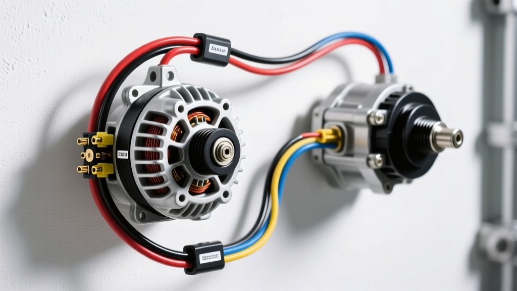
Welcome to the world of automotive electrical diagnostics. When beginners approach auto electric systems, the sheer volume of wiring harnesses, relays, fuse blocks, and control modules can induce immediate paralysis. However, every modern vehicle relies on the same foundational architecture established decades ago. By understanding the core charging and cranking circuits, you build a mental framework that applies to everything from a 1993 Chevrolet C1500 to a modern Silverado. In this guide, we break down the absolute fundamentals using the ubiquitous GM CS130 alternator and the legendary Delco 10MT starter motor as our teaching models. Mastering these specific components will give you the confidence to trace, repair, and upgrade any 12-volt vehicle architecture.
The High-Amperage Core: Battery, Starter, and Alternator
The backbone of any vehicle's electrical network is the high-amperage loop connecting the battery, the starter motor, and the alternator. While modern cars feature complex CAN-bus networks and body control modules, the physical movement of electrons from the battery to the starter, and from the alternator back to the battery, remains governed by basic Ohm's Law. According to the SAE J1128 Low Tension Cable Standard, automotive wire is sized by the American Wire Gauge (AWG) system. Unlike household wiring, auto electric systems require flexible, multi-strand copper wire designed to withstand under-hood heat, constant vibration, and chemical exposure. Using solid-core wire or undersized gauges is a primary cause of parasitic voltage drops, melted harnesses, and premature component failure.
Wire Gauge (AWG) and SAE Color Standards
Proper wire sizing is non-negotiable. The AWG rating dictates the maximum current a wire can safely carry without excessive resistance heating. Below is a foundational reference chart for high-amperage circuits in standard V8 passenger trucks and cars.
| Circuit Application | Recommended AWG | Typical GM Wire Color | Max Amperage Capacity |
|---|---|---|---|
| Battery to Starter | 1/0 AWG or 2 AWG | Red | 250A - 400A |
| Alternator B+ to Battery | 4 AWG or 8 AWG | Red | 80A - 140A |
| Starter Solenoid (S) Feed | 10 AWG or 12 AWG | Purple | 15A - 25A |
| Alternator Ignition/Lamp | 16 AWG or 18 AWG | Pink / Brown | 2A - 5A |
Alternator Fundamentals: The GM CS130 4-Pin Connector
The GM CS130 (Charging System, 130mm stator diameter) is a staple in automotive electrical education. Introduced in the late 1980s and used extensively through the 1990s and 2000s, it utilizes a specific 4-pin rectangular connector that dictates how the internal voltage regulator manages field current. Understanding these four pins is the key to diagnosing undercharging or overcharging conditions.
Terminal Breakdown: S, L, I, and F
- Terminal S (Sense): This is the most critical pin for proper system voltage. The Sense wire (typically 16 AWG Red or Orange) must be routed directly to the positive battery terminal or the main power distribution block. It tells the regulator the actual voltage at the battery. If you mistakenly wire this to the alternator B+ post, the regulator will overcharge the system to compensate for the voltage drop across the main charge wire, potentially boiling the battery acid.
- Terminal L (Lamp): Connected to the dashboard 'GEN' or 'ALT' warning light. When the ignition is ON and the engine is OFF, the regulator grounds this circuit, illuminating the bulb. Once the alternator begins producing AC voltage, the internal diodes block the ground path, turning the light off. A 10-ohm, 1/2-watt resistor is often wired in parallel with the bulb to ensure the regulator 'turns on' even if the dashboard bulb burns out.
- Terminal I (Ignition): A switched 12V source (usually 18 AWG Pink). While some early CS130 setups used this to wake up the regulator, modern implementations often leave this pin empty, relying entirely on the L and S terminals for excitation.
- Terminal F (Field): Used by the Powertrain Control Module (PCM) to monitor the alternator's duty cycle. The PCM uses this PWM (Pulse Width Modulation) signal to trigger electric cooling fans or adjust engine idle speed when high electrical loads are detected.
Starter Motor Circuits: Delco 10MT Solenoid Wiring
The Delco 10MT (10-inch Motor, Through-bolt) starter features three primary external terminals. Understanding the difference between the heavy-gauge power feed and the low-gauge signal wire is crucial for troubleshooting a 'no-crank' condition.
- BAT (B) Terminal: The massive 3/8-inch stud that receives the 1/0 AWG positive cable directly from the battery. This stud is 'hot' at all times and must be covered with a rubber insulator boot to prevent shorting against the engine block.
- SOL (S) Terminal: The spade terminal that engages the pull-in and hold-in coils of the solenoid. In classic GM wiring, this is fed by a 12 AWG Purple wire from the ignition switch's 'Start' position. Expert Tip: Because the ignition switch handles the full solenoid inrush current (often 20+ amps), the contacts inside the switch degrade over time. This causes a voltage drop, resulting in a slow 'click-click-click' no-crank condition. The professional fix is installing a 30-amp Bosch-style relay (Terminal 87 to S-terminal, Terminal 30 to Battery, Terminal 86 to Ignition Start, Terminal 85 to Ground) to carry the heavy load.
- RES (R) Terminal: The bypass terminal. On older points-style ignitions, this sends a full 12V boost to the ignition coil only while the starter is cranking, bypassing the ballast resistor. On modern HEI or coil-on-plug systems, this terminal is left completely disconnected.
Diagnosing the System: Voltage Drop Testing
As noted in Haynes Automotive Electrical Basics, a multimeter set to resistance (Ohms) is practically useless for testing live auto electric systems. The resistance of a single strand of copper wire might read 0.0 ohms on your meter, but under a 100-amp load, that same wire could drop 3 volts and melt. You must test for Voltage Drop under load.
- Set your digital multimeter to DC Volts.
- Place the red probe directly on the battery positive post (not the clamp, the lead post itself) and the black probe on the alternator B+ stud.
- Start the engine and turn on the headlights, rear defroster, and blower motor on high to create a 40A+ electrical load.
- A healthy 4 AWG charge wire should show a voltage drop of less than 0.2V. If you read 0.8V or higher, the wire is undersized, the crimp lugs are corroded internally, or the battery terminals are loose.
- Repeat the test on the ground side: Red probe on the alternator case, black probe on the battery negative post. A reading above 0.1V indicates a poor engine-to-chassis ground strap.
Common Beginner Wiring Mistakes to Avoid
When modifying or repairing vehicle wiring, avoiding these common pitfalls will save you hours of diagnostic headaches:
- Soldering Under-Hood Connections: Solder creates a rigid, brittle joint that will inevitably crack under engine vibration, leading to high resistance and arcing. The OEM standard is to use open-barrel crimps with adhesive-lined heat shrink (like Delphi Packard or Molex terminals) using a proper ratcheting crimper.
- Misrouting the Sense Wire: As mentioned, wiring the CS130 'S' terminal to the alternator B+ post instead of the battery defeats the purpose of the remote sense circuit and guarantees overcharging.
- Ignoring Dielectric Grease: Failing to pack bulkhead connectors and fuse box terminals with dielectric grease allows moisture to create green copper oxide corrosion, which acts as a semiconductor and causes parasitic battery drains.
- Fusing for the Component, Not the Wire: Fuses are designed to protect the wire, not the component. Putting a 60A fuse on a 14 AWG wire because the electric fan draws 40A is a fire hazard. The 14 AWG wire will melt long before the 60A fuse blows. Always size the fuse to the AWG capacity of the wire.
Final Thoughts on Automotive Architecture
Understanding auto electric systems is not about memorizing every wire in a 2,000-page factory service manual. It is about understanding the flow of current, the necessity of low-resistance paths, and the logical switching of control circuits. By mastering the fundamental loops of the CS130 alternator and the Delco starter, you equip yourself with the diagnostic logic required to tackle modern, PCM-controlled charging systems and high-amperage EV architectures. Always disconnect the negative battery terminal before cutting or splicing wires, and invest in a high-quality digital multimeter before beginning your first project.