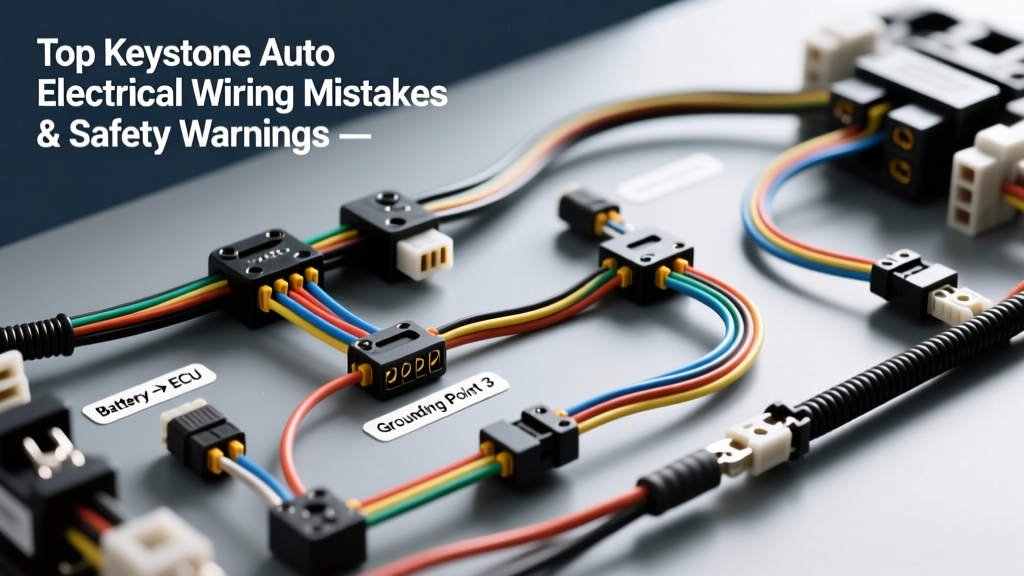
Introduction to Keystone Auto Electrical Systems
When engineering custom wiring harnesses, hot rod electrical networks, or heavy-duty off-road power distribution systems, integrating premium Keystone auto electrical components is a hallmark of professional-grade builds. Keystone Electronics manufactures industry-standard heavy-duty battery terminals (such as the Keystone 355 and 356 series), robust inline fuse holders, and high-current test points. However, even the highest-quality brass and copper components cannot compensate for poor installation practices. In fact, misapplying these components often leads to catastrophic thermal runaway, voltage drop, and electrical fires. This guide details the most common mistakes and critical safety warnings when working with Keystone auto electrical hardware in 12V and 24V vehicle architectures.
Mistake 1: Mismatched Crimp Dies and Open-Barrel Failures
The most frequent failure point in any custom harness is the crimp termination. Keystone heavy-duty terminals are designed for specific wire gauges, typically ranging from 6 AWG up to 1/0 AWG. A critical safety warning involves the use of mismatched crimping dies. Using a generic, uncalibrated crimp tool on a 2 AWG cable destined for a Keystone 355 battery terminal often results in an asymmetric or "open-barrel" crimp that fails to achieve the necessary cold-weld. Under the hood, engine vibration (measured in Hz and peak G-forces) will quickly work an under-crimped wire loose from the terminal barrel.
Furthermore, modern automotive wire adheres to SAE J1128 standards, utilizing thin-wall insulation types like TXL, GXL, and SXL. Standard PVC crimp dies are designed for thicker insulation. When applied to TXL wire, a standard die will crush the copper strands before biting into the insulation, compromising the wire's ampacity and creating a localized high-resistance hotspot. Always use crimp dies specifically profiled for SAE thin-wall automotive wire, and verify the crimp pull-out force meets manufacturer specifications.
Mistake 2: Ignoring Terminal Torque Specifications
Over-tightening or under-tightening the hardware on Keystone auto electrical terminals is a leading cause of alternator output loss and starter circuit failure. Many builders assume that "tighter is better," applying excessive torque to the M6 or M8 brass studs on battery terminals and fuse blocks. Brass is a relatively soft alloy; over-torquing will strip the threads or crack the terminal body, compromising the mechanical integrity of the connection. Conversely, under-torquing allows micro-movements that lead to micro-arcing, oxidation, and eventual thermal melting of the surrounding wire insulation.
Below is the recommended torque specification chart for standard Keystone heavy-duty terminal hardware and common automotive electrical distribution studs. Always use a calibrated inch-pound torque wrench for these connections.
| Hardware Size | Thread Pitch | Recommended Torque (in-lbs) | Common Application |
|---|---|---|---|
| 1/4" (M6) | 1.0 mm / 20 TPI | 45 - 60 in-lbs | Small gauge fuse blocks, relay studs |
| 5/16" (M8) | 1.25 mm / 18 TPI | 70 - 90 in-lbs | Keystone 355 Battery Terminals, Starter lugs |
| 3/8" (M10) | 1.5 mm / 16 TPI | 110 - 140 in-lbs | Main alternator output posts, heavy-duty busbars |
For a comprehensive understanding of terminal mechanical standards, refer to SAE J1284 regarding battery terminal and clamp testing protocols.
Mistake 3: The Dielectric Grease vs. Anti-Oxidant Confusion
A pervasive and dangerous myth in the automotive electrical community is the blanket application of dielectric grease to all mating electrical surfaces. Dielectric grease is, by definition, an electrical insulator. If you pack dielectric grease between the lead battery post and the copper/brass Keystone terminal before tightening, you are intentionally introducing a high-resistance barrier into your main power feed. This resistance generates heat according to Joule's Law (P = I²R), which can melt the terminal and cause a fire.
The correct product for the mating surface of a battery terminal or heavy-duty ground stud is an anti-oxidant compound (such as Noalox), which contains microscopic conductive zinc or copper particles suspended in grease. These particles bite through microscopic oxide layers on the brass and lead, ensuring metal-to-metal contact while the grease base seals out moisture. Dielectric grease should only be applied over the fully torqued and cleaned connection to seal the exterior against water and road salt intrusion. Mixing these two compounds up is a primary cause of voltage drop in custom Keystone auto electrical installations.
Mistake 4: Undersizing the Main Feed to the Fuse Block
When utilizing a centralized Keystone-style fuse block or power distribution module, builders often underestimate the cumulative current draw of the distribution wires. While individual circuits may be protected by 15A or 20A fuses using 14 AWG or 12 AWG wire (color-coded Green and White per standard SAE practices), the main feed wire supplying the fuse block must be sized for the sum of the continuous loads, not just the sum of the fuse ratings.
For example, if a custom off-road vehicle has a 150A alternator and the fused distribution block powers dual cooling fans (40A), a fuel pump (15A), ECU (10A), and lighting (20A), the continuous draw can easily exceed 85A. Using a 4 AWG main feed wire for a 15-foot run from the battery to the engine bay fuse block will result in a voltage drop exceeding 0.5V. This drop starves the ECU and fuel pump of necessary voltage, leading to lean conditions and stalling. For an 85A continuous load over 15 feet, a minimum of 1/0 AWG (color-coded Red) stranded copper wire is required to maintain a voltage drop below 0.2V. Always calculate voltage drop using the specific resistivity of copper (10.37 ohms per circular mil foot) rather than relying on generic ampacity charts that do not account for distance.
Troubleshooting Decision Tree: Voltage Drop at the Keystone Terminal
If your vehicle exhibits slow cranking, dimming headlights, or alternator whine, the Keystone auto electrical connections at the battery and starter are the first suspects. Follow this systematic voltage drop testing procedure using a digital multimeter (DMM) set to DC Volts.
- Step 1: The Positive Side Test. Connect the DMM's red probe directly to the alternator's B+ output post and the black probe directly to the battery's positive post. Start the engine and turn on all electrical loads (headlights, blower motor). The DMM should read less than 0.3V. If it reads higher, proceed to Step 2.
- Step 2: Isolating the Keystone Terminal. Move the black probe from the battery post to the cable lug crimped inside the Keystone terminal. If the voltage drop disappears (reads near 0.0V), the internal resistance is between the battery post and the terminal body—indicating corrosion, improper torque, or the misuse of insulating dielectric grease.
- Step 3: The Crimp Joint Test. Move the black probe to the wire insulation, right where it enters the terminal barrel. If the voltage spike occurs here, the cold-weld crimp has failed. The wire strands are oxidizing inside the barrel. The terminal must be cut off and re-crimped with the correct TXL-profiled die.
- Step 4: The Ground Side Verification. Repeat the process on the negative side. Place the red probe on the battery negative post and the black probe on the engine block. A reading above 0.1V indicates a poor engine-to-chassis ground strap or a corroded Keystone ground terminal at the battery negative post.
Conclusion: Precision is Non-Negotiable
Building a reliable vehicle electrical system requires more than just purchasing premium Keystone Electronics components; it demands strict adherence to metallurgical, mechanical, and electrical standards. By avoiding mismatched crimp dies, respecting precise torque specifications, understanding the chemical differences between anti-oxidant and dielectric compounds, and properly sizing main feed conductors, you ensure that your Keystone auto electrical system will perform flawlessly under the harshest automotive conditions. Always prioritize SAE standards and verified testing methods over garage myths to keep your custom build safe, reliable, and road-worthy.