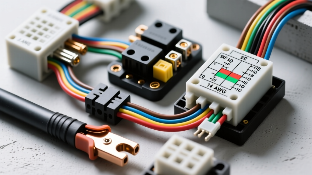
Defining Master Auto Electric Standards
Achieving master auto electric proficiency requires transitioning from basic continuity testing to dynamic circuit analysis under load. Novice technicians often rely on static resistance measurements with a multimeter, which can yield false-positive results on circuits suffering from severe corrosion or strand breakage. A true master technician utilizes voltage drop testing under operational load, understands the thermal derating of wire harnesses, and adheres strictly to OEM and SAE terminal crimp specifications. This technical reference outlines the foundational specifications, diagnostic thresholds, and component architectures required for master-level automotive electrical diagnostics and repair.
SAE J1128 and ISO 6722 Primary Wire Specifications
Automotive primary wire is governed by strict standards to ensure current-carrying capacity and thermal resistance. In North America, SAE J1128 dictates the specifications for battery and primary cables, while European and Asian platforms frequently utilize ISO 6722 metric sizing. Master technicians must understand the cross-sectional equivalencies and the impact of stranded copper vs. solid core on flex life and high-frequency signal transmission.
Modern high-temperature engine bays require XLPE (Cross-Linked Polyethylene) insulation rather than standard PVC, as XLPE maintains dielectric integrity up to 150°C, whereas PVC degrades rapidly above 105°C. When sizing wire for custom harnesses or heavy-duty accessory installations (e.g., electric AC compressors or high-output alternators), always calculate the voltage drop over the total circuit length (power and ground combined).
| AWG Size | Metric (mm²) | Strand Count (Typical) | Max Resistance (Ω/1000ft @ 20°C) | Max Ampacity (Chassis Wiring)* |
|---|---|---|---|---|
| 18 AWG | 0.8 mm² | 16 | 6.51 | 10A - 14A |
| 16 AWG | 1.3 mm² | 19 | 4.09 | 13A - 18A |
| 14 AWG | 2.0 mm² | 19 | 2.58 | 15A - 25A |
| 12 AWG | 3.0 mm² | 19 | 1.62 | 20A - 35A |
| 10 AWG | 5.0 mm² | 19 | 1.02 | 30A - 50A |
| 8 AWG | 8.0 mm² | 19 | 0.64 | 40A - 70A |
*Note: Ampacity varies based on ambient temperature, harness bundling (derating factors), and insulation type. Always consult the specific OEM wiring manual for continuous vs. peak load ratings.
ISO Relay Pinouts and Coil Diagnostics
Electromechanical relays are the workhorses of the automotive electrical architecture. Master auto electric diagnostics require more than simply swapping a relay; it involves verifying the control side (coil) and the load side (contacts) independently. Standard ISO Mini relays utilize the DIN 72552 terminal designation system. The coil circuit typically draws between 120mA and 180mA, while the load contacts are rated for 30A to 40A continuous.
When testing a relay coil, a master technician checks not only for resistance but also for inductive flyback suppression. Many modern OEM relays contain internal clamping diodes or resistors. Applying reverse polarity to a diode-protected relay during a bench test will result in an open circuit reading, leading to a false condemnation if the technician is unaware of the internal architecture.
Standard ISO Mini Relay (5-Pin) Terminal Reference
| Terminal (DIN) | Function | Typical Specification / Test Parameter |
|---|---|---|
| Pin 86 | Coil Power Input (+) | 12V nominal; verify < 0.2V drop from source under load. |
| Pin 85 | Coil Ground (-) | PCM or BCM controlled ground; verify < 0.1V drop to chassis. |
| Pin 30 | Load Power Input (+) | Fused B+ feed; must maintain within 0.5V of battery voltage. |
| Pin 87 | Load Output (Normally Open) | Max contact voltage drop: 0.15V at rated load (e.g., 30A). |
| Pin 87a | Load Output (Normally Closed) | Disengages when coil is energized; rarely used in modern auto HVAC. |
For deeper insights into relay architectures and solid-state alternatives, refer to the Bosch Mobility Solutions electrical systems documentation.
Master-Level Voltage Drop Thresholds
Voltage drop testing is the definitive method for identifying high-resistance faults in the master auto electric repertoire. Resistance testing with an ohmmeter uses less than a milliamp of current, which can easily bridge across a single strand of copper or a layer of conductive corrosion. Voltage drop testing forces the circuit to operate under its designed amperage load, revealing the true operational state of the conductors and terminals.
The universally accepted master-level thresholds for 12-volt automotive systems dictate that no single connection, switch, or fuse should drop more than 0.10V (100mV). For heavy cable runs, the total allowable drop is proportional to the wire gauge and length, but strict limits apply to critical powertrain circuits.
| Circuit Component | Maximum Allowable Voltage Drop | Common Failure Modes |
|---|---|---|
| Battery Cable (Positive or Negative) | 0.50V (Total Cable) | Internal strand corrosion, loose terminal swaging. |
| Starter Motor B+ Feed | 0.50V (Under Cranking Load) | Undersized aftermarket cables, corroded solenoid contacts. |
| Engine Block to Chassis Ground | 0.10V (Under Cranking Load) | Paint under ground strap bolt, frayed braided strap. |
| Alternator Output (B+ to Battery) | 0.20V (At Max Alternator Output) | Mega-fuse degradation, undersized charge wire. |
| PCM Power / Sensor Ground | 0.05V (50mV) | Splice pack corrosion, pushed-back terminals in ECU connector. |
| Standard Fuse / Fusible Link | 0.10V (At Rated Load) | Micro-fractures in element, degraded female terminal grip. |
Terminal Crimp and Connector Standards
A master technician never relies on solder for primary automotive wire splicing in high-vibration or high-tension areas. Solder creates a rigid stress riser that leads to wire fatigue and breakage just outside the solder joint. Instead, master auto electric repair relies on open-barrel or closed-barrel terminal crimps that create a cold-weld gas-tight seal. Aptiv (formerly Delphi) Connection Systems defines strict pull-test and millivolt drop criteria for their industry-standard Metri-Pack and Weather-Pack lines.
Crimp Anatomy and Inspection Criteria
When utilizing open-barrel terminals (such as Metri-Pack 150, 280, or 630 series), the crimp must exhibit the following characteristics:
- Conductor Bellmouth: A small flare of wire strands visible just ahead of the terminal crimp wings (typically 0.5mm to 1.0mm) to ensure all strands are captured and none are sheared off by the tooling.
- Insulation Grip: The rear crimp wings must securely clamp the wire insulation without piercing it, providing strain relief.
- Brush: The wire strands should protrude slightly past the front of the conductor crimp wings (maximum 1mm) to verify full insertion depth.
- Terminal Lock Engagement: When inserted into the plastic connector housing, the terminal must engage the primary plastic lock (and secondary TPA/CPA lock if equipped). A master tech always performs a 10-lb pull-test on every terminated wire before sealing the connector.
DIN 72552 Terminal Designations in Modern Architecture
While modern CAN-bus networks have reduced the reliance on hardwired ignition feeds, understanding DIN 72552 terminal designations remains critical for diagnosing legacy circuits, starter solenoids, and aftermarket integrations. Terminal 30 represents constant battery power. Terminal 15 represents switched ignition power. Terminal 31 is the chassis ground. Terminal 50 is the starter control circuit. When integrating electric AC compressors or auxiliary cooling fans, master technicians utilize Terminal 15 logic or CAN-triggered relays to ensure parasitic draw is eliminated when the vehicle enters sleep mode.
Mastering these specifications, diagnostic thresholds, and physical repair standards elevates a technician from a parts-swapper to a true master auto electric diagnostician. Always reference the specific OEM service information for proprietary pinouts and module-specific sleep-state current draw limits.