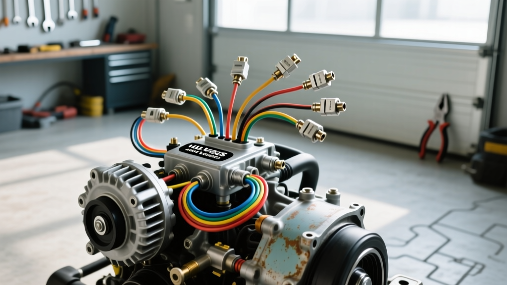
Upgrading Classic Charging Systems with Sergios Auto Electric
Restomodding a classic muscle car or vintage truck often exposes the severe limitations of factory electrical systems. Stock externally regulated alternators typically peak between 37 and 63 amps, which is entirely inadequate for modern electric cooling fans, electronic fuel injection (EFI), and high-wattage halogen lighting. The Sergios Auto Electric 140A High-Output Alternator and Wiring Harness Kit resolves this bottleneck by integrating a modern, internally regulated 1-wire/3-wire convertible alternator with heavy-gauge cabling. This guide details the exact installation protocol, wire routing, and pinout configurations required to safely integrate this system into a classic vehicle architecture.
Required Tools and Safety Preparation
Before beginning any high-amperage wiring modification, disconnect the negative battery terminal and isolate it to prevent accidental arcing. Working with 140A+ circuits requires proper tooling to ensure low-resistance connections that will not melt under continuous load.
- Wire Strippers & Crimpers: Ratcheting closed-barrel crimpers for 4 AWG and 16-18 AWG terminals.
- Heat Gun: For sealing adhesive-lined marine-grade heat shrink.
- Digital Multimeter (DMM): Capable of measuring DC voltage and resistance (Ohms).
- Torque Wrench: For alternator mounting bolts and terminal lugs.
- Wire Loom & Split Loom Tubing: For abrasion protection across the firewall and chassis.
Kit Component Specifications
The Sergios Auto Electric kit utilizes SAE J1128 compliant cross-linked polyethylene (XLPE) insulated wire, which withstands engine bay temperatures up to 125°C. Below is the specification chart for the included harness components.
| Component | Wire Gauge / Rating | Insulation Color | Function |
|---|---|---|---|
| Main Charge Cable | 4 AWG (175A capacity) | Red | Carries bulk current from alternator B+ to battery/starter. |
| Voltage Sense Wire | 16 AWG | Pink | Provides real-time battery voltage feedback to internal regulator. |
| Exciter / Lamp Wire | 18 AWG | White | Triggers regulator turn-on via ignition switch and dash lamp. |
| Inline Fuse Holder | 175A ANL Fuse | N/A | Protects main charge cable from dead-short thermal runaway. |
| Regulator Pigtail | Delphi Packard 2-Pin | Black Loom | Weather-sealed connector for sense and exciter circuits. |
Step-by-Step Installation Procedure
Step 1: Alternator Mounting and Belt Alignment
Install the high-output alternator using the factory or aftermarket bracketing. Ensure the serpentine or V-belt pulley aligns perfectly with the crankshaft and water pump pulleys. Misalignment causes premature bearing failure and belt shedding. Torque the main mounting bolts to 35-40 lb-ft depending on the specific bracket hardware. Critical: The alternator case must have a clean, bare-metal ground path to the engine block. Scrape away any paint or powder coating from the mounting ears to ensure a solid case ground.
Step 2: Routing the 4 AWG Main Charge Cable
Route the 4 AWG Red main charge cable from the alternator B+ terminal to the starter solenoid battery post or a dedicated positive distribution bus bar. Do not route this cable near the exhaust manifolds, sharp metal edges, or the distributor cap to prevent electromagnetic interference (EMI) and insulation melt-down. According to American Autowire best practices, all heavy-gauge cables crossing the firewall or running along the chassis must be encased in split-loom tubing and secured with nylon zip ties every 8 inches.
Step 3: Fusing the Main Circuit
Install the 175A ANL fuse holder on the 4 AWG Red cable. Per automotive electrical safety standards, the main circuit protection must be located within 18 inches of the battery positive terminal or the starter solenoid battery post. This ensures that if the cable chafes against the chassis anywhere along its run, the fuse will blow before the wire can ignite.
Step 4: Wiring the Regulator Pigtail (Sense and Exciter)
The internal voltage regulator requires two low-amperage signals to function correctly and maintain a steady 14.2V - 14.4V output. Connect the Delphi Packard 2-pin pigtail to the alternator regulator port. Refer to the pinout table below for exact wire routing.
| Pin Designation | Wire Color | Destination | Technical Notes |
|---|---|---|---|
| Pin A (Sense) | 16 AWG Pink | Battery Positive or Ignition Switch | For best results, run this wire directly to the battery positive or the main side of the ignition switch to read true system voltage, avoiding voltage drop from the alternator case. See the Madelectrical Remote Sensing Guide for detailed theory. |
| Pin B (Exciter) | 18 AWG White | Ignition Switch (Run Position) | Must be connected to a switched 12V source. If wiring to a dashboard 'GEN' or 'ALT' indicator lamp, a 565-ohm bypass resistor must be wired in parallel to ensure the regulator receives adequate initial excitation current. |
Step 5: Terminal Crimping and Sealing
Do not rely on solder for high-amperage 4 AWG connections; solder can wick into the wire strands, creating a rigid point that will eventually fatigue and break under engine vibration. Use a ratcheting closed-barrel crimper for the 5/16" ring terminals. Slide a piece of dual-wall, adhesive-lined heat shrink over the wire before crimping. Once crimped, apply heat until the adhesive oozes out the ends, creating a waterproof, corrosion-proof seal.
Validation and Voltage Drop Testing
Once all connections are secured and the battery is reconnected, start the engine and allow it to idle. Turn on the headlights, blower motor, and electric cooling fans to place the system under load. Use your DMM to perform a voltage drop test across the charging circuit.
How to Perform the Voltage Drop Test
- Set the DMM to DC Volts.
- Place the red probe on the alternator B+ terminal and the black probe on the battery positive post. Under load, the reading must be less than 0.20V. A higher reading indicates excessive resistance in the 4 AWG cable, a poor crimp, or undersized wiring.
- Place the red probe on the battery negative post and the black probe on the alternator case housing. Under load, the reading must be less than 0.10V. A higher reading indicates a poor engine-to-chassis ground or a painted alternator mounting ear.
Troubleshooting Common Installation Issues
Even with a premium Sergios Auto Electric kit, installation errors can lead to charging anomalies. Use this diagnostic tree to resolve common issues:
- Symptom: Alternator not charging (Dash lamp stays on).
- Cause 1: No 12V at the White Exciter wire. Fix: Check the ignition switch 'Run' circuit and verify the 565-ohm bypass resistor if using an LED dash lamp (LEDs do not pass enough current to excite the regulator).
- Cause 2: Blown 175A ANL fuse. Fix: Inspect the 4 AWG cable for a dead short to ground before replacing the fuse.
- Symptom: Battery overcharging (>15.0V).
- Cause: High resistance or open circuit in the Pink Sense wire. The regulator defaults to maximum output when it loses the sense signal. Fix: Check the Pin A connection and ensure the sense wire is not routed through a relay that drops voltage.
- Symptom: Whining noise in the audio system.
- Cause: Alternator ripple current entering the chassis ground. Fix: Verify the engine-to-chassis ground strap is intact, clean, and free of corrosion. Ensure the alternator case ground is bare metal.
Final Inspection
After the initial test drive, allow the engine to cool and re-inspect all terminals. Thermal cycling can sometimes cause poorly crimped lugs to loosen. Verify that the 4 AWG cable is not resting against the exhaust and that the Delphi Packard connector is fully seated and locked. Proper installation of the Sergios Auto Electric harness guarantees a robust, reliable charging system capable of supporting modern automotive electronics for years to come.