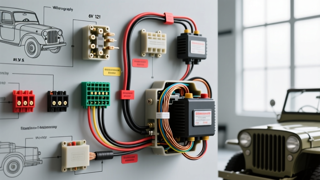
Decoding the Willis Auto Electric Legacy: Willys-Overland Architecture
When enthusiasts and restorers search for Willis auto electric diagrams, they are almost universally navigating the complex, often misunderstood electrical architecture of the legendary Willys-Overland Jeep CJ series (CJ-2A, CJ-3A, CJ-3B, and early CJ-5). Originally engineered around a 6-volt, positive-ground electrical system, these early military and civilian platforms present unique challenges for modern restoration and daily driving. The transition from the original Autolite generators to modern 12-volt negative-ground alternator setups requires a meticulous understanding of wire gauges, voltage drop tolerances, and circuit protection.
In this advanced technical deep dive, we will dissect the original 6V harness routing, outline the exact specifications for a bulletproof 12-volt negative-ground conversion, and provide actionable troubleshooting trees for the most common Willys starting and charging system failures. Whether you are retaining the original 6V positive ground or upgrading to a 12V Delco alternator, understanding the foundational Willis auto electric principles is critical to preventing harness fires and voltage starvation.
Original 6-Volt Positive Ground Architecture
The original Willys CJ electrical system was designed around simplicity and wartime supply chain realities. The system utilized a 40-amp Autolite generator, a mechanical voltage regulator, and a cloth-braided wiring harness. In a positive-ground system, the positive terminal of the battery is connected to the chassis, while the negative terminal feeds the starter solenoid and primary electrical loads.
Original Harness Wire Color Codes and AWG Specs
- Battery to Starter Solenoid: 2 AWG (Black or uninsulated braided copper). High amperage draw (150A+ during cranking) requires minimal resistance.
- Generator to Ammeter: 10 AWG (Black). Must handle the full 40A generator output without excessive voltage drop.
- Ammeter to Ignition/Lighting Switch: 12 AWG (Yellow/Red tracers).
- Lighting Circuits (Headlamps/Tail lamps): 14 AWG. Original cloth-covered wires often deteriorate, exposing copper to the steel tub and frame, causing dead shorts on a positive ground system.
Expert Note: If you are retaining the 6V system, you must adhere to SAE J1128 standards for low-tension primary cable, ensuring you use SXL (cross-linked polyethylene) insulated wire to withstand the high under-hood temperatures of the L134 Go-Devil engine.
The 12-Volt Negative Ground Conversion: Advanced Specifications
Upgrading a Willys CJ to a 12-volt negative-ground system is the most common modification in the Willis auto electric community. This conversion allows for the use of modern halogen or LED lighting, high-torque gear-reduction starters, and reliable 1-wire or 3-wire alternators. However, simply swapping the battery and alternator will result in blown bulbs, melted ignition switches, and destroyed gauge clusters if the supporting circuits are not properly re-engineered.
Component Upgrade & Wiring Specification Chart
| Component / Circuit | Original 6V Spec | 12V Upgrade Spec | Required Wire Gauge (AWG) |
|---|---|---|---|
| Alternator Output (Stud to Batt) | Generator (10 AWG) | Delco 10-SI (63A-94A) | 8 AWG (Minimum 10 AWG for short runs) |
| Starter Motor | 6V Series-Wound | 12V Gear-Reduction (PMGR) | 2 AWG or 1/0 AWG |
| Ignition Coil Feed | Direct 6V (No Resistor) | 12V via 1.5Ω Ballast Resistor | 14 AWG |
| Headlamp Circuit | 6V Sealed Beam (14 AWG) | 12V H4 Halogen/LED w/ Relays | 12 AWG (Power), 16 AWG (Trigger) |
| Gauge Cluster Feed | Direct 6V Ammeter | 12V w/ Instrument Voltage Regulator (IVR) | 16 AWG |
Delco 10-SI Alternator Integration & Pinout Configuration
The Delco Remy 10-SI alternator is the gold standard for Willys 12V conversions due to its internal voltage regulation and widespread availability. To properly integrate this into a Willis auto electric harness, you must understand the 2-pin connector on the alternator case.
- Pin #1 (Voltage Sense / Lamp): This pin must be connected to a switched 12V source that is active only when the ignition is in the 'ON' or 'RUN' position. It excites the rotor field. If you are using a dash-mounted charge indicator lamp, wire Pin #1 through the bulb. If using a standard dash light, wire Pin #1 directly to the ignition switch 'IGN' terminal.
- Pin #2 (Voltage Reference): This pin tells the internal regulator the actual system voltage. For the most accurate charging profile, run a dedicated 14 AWG sense wire from Pin #2 directly to the positive terminal of the battery or the main distribution block. Do not simply jumper Pin #1 and Pin #2 together at the alternator; this causes the regulator to sense voltage at the alternator case, leading to undercharging at the battery due to harness voltage drop.
For detailed alternator teardowns and bench testing procedures, refer to the Kaiser Willys technical archives, which provide excellent cross-referencing for early Jeep charging systems.
Starter Solenoid & Ignition Circuit Troubleshooting
The Willys CJ utilizes a heavy-duty, chassis-mounted starter solenoid (often a Ford-style 3-post or 4-post relay). A common failure mode in upgraded 12V systems is the 'no-crank' condition, often misdiagnosed as a dead starter.
Voltage Drop Testing Decision Tree
- Symptom: Solenoid clicks, but starter does not turn.
- Test: Measure voltage drop across the solenoid's main battery and starter terminals while cranking.
- Pass: Drop is less than 0.2V. (Issue is internal to the starter motor or poor starter ground).
- Fail: Drop is greater than 0.5V. (Solenoid internal contacts are pitted/carbonized. Replace solenoid).
- Symptom: No click at the solenoid when key is turned to 'START'.
- Test: Measure voltage at the 'S' (trigger) terminal on the solenoid while holding the key in 'START'.
- Result A: 0V present. (Fault lies in the ignition switch, neutral safety switch, or 14 AWG trigger wire).
- Result B: 10V+ present. (Fault lies in the solenoid coil ground or the solenoid pull-in coil is open).
Grounding Protocols: The Achilles Heel of the CJ Tub
The most pervasive issue in any Willis auto electric project is inadequate grounding. The Willys CJ body is mounted to the frame via rubber isolation bushings. This means the steel tub is electrically isolated from the chassis frame. If you mount a tail light, fuel sender, or dash gauge to the body tub without a dedicated ground wire, the circuit will attempt to ground through hinges, steering column bearings, or throttle linkages, resulting in erratic behavior and melted wiring.
Best Practices for 12V Grounding
- Engine to Frame: Use a minimum 2 AWG braided ground strap from the engine block to the chassis frame rail. Ensure paint and powder coating are scraped away to bare metal, secured with a star washer.
- Frame to Tub: Run a dedicated 8 AWG ground wire from the main frame rail to a clean, bare-metal spot on the body tub near the firewall.
- Lighting Pigtails: Never rely on the light housing for a ground. Solder a 16 AWG black pigtail directly to the brass base of every bulb socket, and terminate it to a centralized, star-washed ground bus on the chassis.
Protecting the Ignition Switch from High Amperage
The original Willys ignition and lighting switches were designed to carry the total amperage of the vehicle's 6V loads. When upgrading to 12V, especially if adding high-amp accessories like electric cooling fans or off-road light bars, routing all power through the original dashboard switch will cause the internal copper contacts to overheat and melt.
To preserve the vintage Willis auto electric dashboard aesthetics while ensuring modern reliability, you must implement a relay-controlled architecture. Use the original dashboard switch merely as a low-amperage trigger (drawing less than 2 amps) to activate heavy-duty 30A or 40A automotive relays mounted under the hood. The relays then draw power directly from the battery via appropriately fused 10 AWG or 12 AWG feed wires, bypassing the fragile vintage switch entirely. This hybrid approach maintains the classic look while adhering to modern NHTSA and SAE electrical safety standards regarding circuit protection and thermal management.