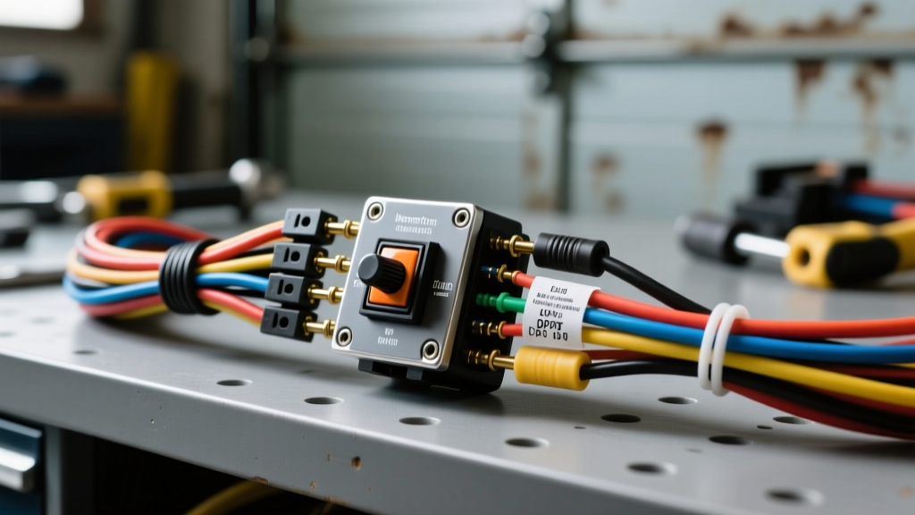
The Hidden Dangers of DPDT Momentary Switch Installations
A 3 position momentary rocker switch (often configured as MOM-OFF-MOM) is the undisputed backbone of heavy-duty automotive and marine accessories. Whether you are wiring a 12,000-lb off-road winch, a hydraulic snow plow, a dump bed hoist, or a marine windlass, these switches provide the critical directional control required for DC motor reversal. However, because these accessories draw massive amounts of current, the control circuits governing them are highly unforgiving of poor workmanship.
As an automotive electrical specialist, I see the aftermath of botched custom installations daily: melted dash panels, fried control modules, and switches that literally weld themselves shut under load. Understanding the electrical physics and mechanical limitations of a Double Pole Double Throw (DPDT) momentary switch is mandatory for a safe build. Below, we break down the most catastrophic wiring mistakes and the safety protocols required to prevent them.
Mistake #1: Switching High-Amperage Loads Directly (The Melted Switch Syndrome)
The single most dangerous mistake an installer can make is routing the primary motor load directly through the rocker switch contacts. A standard heavy-duty automotive rocker switch is rated for a maximum continuous load of 20 amps to 30 amps at 12V DC.
Consider a standard 12,000-lb winch. Under maximum stall load, the winch motor can draw upwards of 400 amps. If you attempt to wire the winch motor directly to the switch terminals, the internal copper contacts will instantly overheat, arc, and weld together. This results in a runaway winch that cannot be turned off, posing a lethal safety hazard and guaranteeing a burned-out motor or severed cable.
The Safety Fix: Solenoid and Contactor Integration
The 3 position momentary rocker switch must only carry the control circuit current, which typically draws less than 5 amps. You must use the switch to trigger a heavy-duty solenoid (like an Albright DC contactor) or a 4-post winch relay. The switch sends a low-current 12V signal to the solenoid coils, which then mechanically closes the high-current contacts to power the motor. Always install a primary inline ANL or Class-T fuse (e.g., 250A for a 12k winch) within 18 inches of the battery positive terminal to protect the main load cables.
Mistake #2: Miswiring the 6-Pin Polarity Reversing Pinout
To reverse the direction of a DC motor (e.g., winch IN vs. winch OUT), you must reverse the polarity of the voltage reaching the motor. A standard 6-pin DPDT momentary switch acts as a manual H-Bridge to accomplish this. Misunderstanding the internal contact topology leads to dead shorts, blown fuses, and reversed directional logic.
Many DIY installers assume the pins are laid out in a simple series. In reality, the switch relies on cross-jumpering to route power and ground to the correct solenoid coils depending on the rocker's physical position. Below is the industry-standard pinout configuration for a 6-pin MOM-OFF-MOM polarity reversing switch.
| Pin Number | Internal Connection Logic | External Wiring Destination |
|---|---|---|
| Pin 1 | Jumpered to Pin 6 | +12V Fused Ignition or Battery Source |
| Pin 2 | Pole 1 Common (Output) | Solenoid Coil A (e.g., Winch IN / Spool IN) |
| Pin 3 | Jumpered to Pin 4 | Vehicle Chassis Ground (-) |
| Pin 4 | Jumpered to Pin 3 | Vehicle Chassis Ground (-) |
| Pin 5 | Pole 2 Common (Output) | Solenoid Coil B (e.g., Winch OUT / Spool OUT) |
| Pin 6 | Jumpered to Pin 1 | +12V Fused Ignition or Battery Source |
How the H-Bridge Logic Works
- Rocker Pressed UP: Internally connects Pin 2 to Pin 3 (Ground), and Pin 5 to Pin 6 (+12V). Coil A receives ground, Coil B receives power. Motor runs Direction 1.
- Rocker Released (CENTER): All internal connections open. Circuit is dead. Motor stops safely.
- Rocker Pressed DOWN: Internally connects Pin 1 to Pin 2 (+12V), and Pin 4 to Pin 5 (Ground). Coil A receives power, Coil B receives ground. Motor runs Direction 2.
For deeper reference on switch topologies and contact ratings, consult the Littelfuse Rocker Switch Guides, which provide exact internal schematics for DPDT momentary architectures.
Mistake #3: Using Undersized Control Wiring and PVC Insulation
While the control circuit only carries a few amps, voltage drop over long distances (such as routing from the engine bay to the cabin dashboard) can prevent the solenoid coils from fully engaging. A partially engaged solenoid creates high resistance, generating massive heat and eventually melting the control wires.
Furthermore, using cheap, off-the-shelf PVC-insulated wire (like THHN or standard trailer wire) in an engine bay is a severe fire hazard. Engine bays routinely exceed 100°C (212°F). Standard PVC insulation melts and shorts against the chassis at these temperatures.
The Safety Fix: SAE J1128 GXL/TXL Wire
Always use cross-linked polyethylene (XLPE) insulated wire that meets the SAE J1128 Low Tension Primary Cable standard. GXL or TXL wire features a thin-wall insulation rated for continuous operation up to 125°C (257°F) and offers superior resistance to abrasion and chemical exposure. For control circuits running over 10 feet, use 14 AWG TXL wire rather than 16 AWG to eliminate voltage drop across the solenoid coils. Use a dedicated 10A or 15A inline ATC blade fuse for this control circuit.
Mistake #4: Ignoring IP68 Ingress Ratings for Exterior Mounts
Mounting a standard interior dashboard rocker switch on the exterior of a truck bed, on a marine center console, or on an exposed bumper winch plate guarantees premature failure. Standard switches are rated IP40 or IP50, meaning they offer zero protection against water ingress. When water penetrates the switch housing, it bridges the gap between the +12V input pins and the ground pins, causing a parasitic draw that will drain your battery dead overnight, or worse, cause an electrical fire.
For any installation exposed to the elements, you must specify an IP68-rated momentary switch. IP68 switches feature silicone boots, sealed internal reed or micro-switch mechanisms, and epoxy-potted terminals that completely block moisture and corrosive road salts.
Mistake #5: Poor Terminal Crimps and Galvanic Corrosion
The physical connection at the switch terminals is a frequent point of failure. Using cheap, non-insulated vinyl crimp terminals without a proper ratcheting crimp tool results in 'cold crimps.' A cold crimp has high electrical resistance; under the 5-amp draw of a solenoid coil, this resistance generates enough heat to shrink the vinyl, expose bare copper, and invite corrosion.
Professional Termination Protocol
- Strip Precision: Strip the TXL wire exactly to the barrel depth of the terminal. No bare copper should be visible outside the metal crimp barrel.
- Tooling: Use a ratcheting open-barrel or closed-barrel crimp tool (depending on terminal type) to ensure uniform compression. A pull-test should require over 30 lbs of force to separate the wire.
- Sealing: Use adhesive-lined heat shrink terminals (such as 3M EPS300). When heated, the inner wall of meltable thermoplastic adhesive flows into the wire strands, creating a 100% waterproof environmental seal that prevents capillary action from drawing moisture up into the switch housing.
Symptom-Cause-Fix Decision Tree
When a 3 position momentary rocker switch circuit fails, use this diagnostic tree to isolate the fault safely without risking a short circuit.
- Symptom: Winch/Motor runs in only ONE direction.
- Cause A: Blown inline fuse on the control circuit for Coil A or Coil B. Fix: Replace fuse and check for pinched wires.
- Cause B: Failed solenoid coil. Fix: Test solenoid coil resistance with a multimeter (should read 10-40 ohms). Replace solenoid if open.
- Cause C: Internal switch contact failure on one pole. Fix: Replace DPDT switch.
- Symptom: Switch gets hot to the touch and smells like burning plastic.
- Cause: Direct load switching or severely undersized wiring causing voltage drop and heat buildup. Fix: IMMEDIATELY disconnect battery. Rewire using a heavy-duty contactor so the switch only carries the coil trigger current.
- Symptom: Motor runs continuously even when switch is released (Center OFF).
- Cause: Solenoid contacts have welded shut due to high-amperage arcing. Fix: Disconnect main battery power immediately. Replace the winch contactor/solenoid pack. Refer to Warn Industries Installation Manuals for proper contactor duty-cycle limits.
- Symptom: Battery drains overnight when vehicle is parked.
- Cause: Moisture ingress in an unsealed switch bridging +12V to the solenoid trigger wire, or wiring the switch to constant +12V instead of an ignition-switched source. Fix: Upgrade to IP68 sealed switch and route the +12V feed (Pins 1 & 6) through an ignition relay or dashboard accessory circuit.
Final Safety Directives
Custom automotive wiring is not an area for guesswork. A 3 position momentary rocker switch is a precision control device, not a primary power delivery component. By strictly adhering to DPDT H-bridge pinout logic, utilizing SAE J1128 rated TXL wiring, integrating heavy-duty contactors, and executing adhesive-sealed crimp terminations, you ensure your auxiliary accessories operate reliably and safely in the harshest environments. Always test the completed control circuit with a digital multimeter and a dummy load before connecting the final high-amperage motor leads.