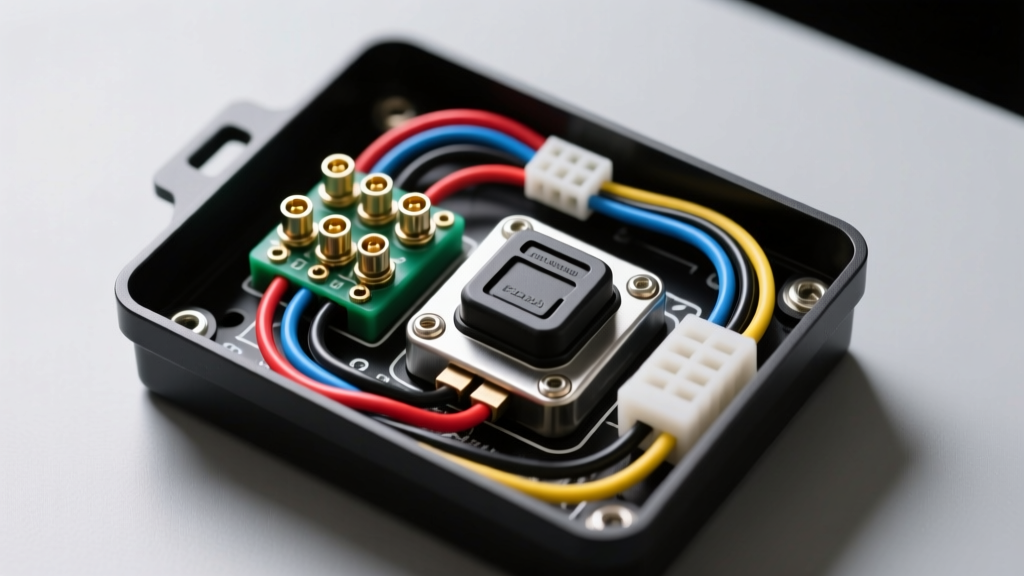
Complete Wiring Diagram Walkthrough: Rocker Switch Cover Guard Integration
When integrating high-draw 12V accessories like winch contactors, onboard air compressors, or locking differentials into your vehicle's electrical system, accidental actuation is not just an inconvenience—it is a critical safety hazard. A standard dashboard toggle can easily be bumped by a knee or engaged by shifting cargo. This is where a rocker switch cover guard becomes essential. Often referred to as a missile launch cover or actuator guard, this mechanical barrier prevents unintended engagement while protecting the underlying switch from moisture, UV degradation, and physical impact.
In this comprehensive wiring diagram walkthrough, we will detail the exact electrical routing required to pair a 5-pin SPST (Single Pole Single Throw) Carling V-Series Contura rocker switch with a hinged cover guard, a standard Bosch-style 40A automotive relay, and a high-current accessory. We will cover wire gauge selection based on SAE J1128 Low Tension Primary Cable standards, precise pinout configurations, and the mechanical installation parameters required for the guard bezel.
The 5-Pin Rocker Switch Wiring Diagram Walkthrough
The most common switch used in off-road and custom automotive builds is the Carling V-Series Contura II or III. These switches feature an IP68 waterproof seal, which is vital when mounting switches in open cabins (like a Jeep Wrangler) or exterior panels. However, adding a rocker switch cover guard provides a secondary physical seal and prevents the internal rocker mechanism from being forced past its detent by accidental pressure.
Below is the logical flow of our wiring diagram for a high-draw accessory protected by a guarded rocker switch:
- Power Source: 12V Battery (+) routed through a 40A MAXI fuse to the Relay (Pin 30).
- Switch Ignition Source: 12V Ignition-switched source routed to the Switch (Pin 6) and Switch (Pin 3).
- Relay Trigger: Switch (Pin 7) routes to the Relay Coil (Pin 86).
- Ground Return: Relay Coil (Pin 85) and Switch LED (Pin 2) route to a dedicated chassis ground bus bar.
- Accessory Load: Relay Output (Pin 87) routes to the accessory positive terminal.
Pinout Configuration and Wire Color Codes
To maintain consistency and adhere to standard automotive electrical troubleshooting practices, we utilize specific AWG sizes and color codes. According to Blue Sea Systems circuit protection guidelines, the switch circuit should be protected by a secondary low-amperage fuse if tapped directly from the battery, but since we are tapping an ignition-switched fuse panel via an Add-A-Circuit, the panel's existing 5A or 10A fuse provides adequate protection for the 18 AWG switch wiring.
| Switch Pin | Function | Wire Color | AWG Size | Destination |
|---|---|---|---|---|
| Pin 2 | LED Ground Return | Black | 18 AWG | Chassis Ground Bus |
| Pin 3 | LED Illumination Source | Red | 18 AWG | Ignition 12V (Add-A-Circuit) |
| Pin 6 | Main Power In (Load) | Yellow | 14 AWG | Ignition 12V (Add-A-Circuit) |
| Pin 7 | Main Power Out (Load) | Blue | 14 AWG | Relay Pin 86 (Coil +) |
| Pin 8 | Not Connected (NC) | N/A | N/A | Unused in SPST Configuration |
Integrating the Cover Guard: Mechanical and Electrical Safety
While the rocker switch cover guard itself is a mechanical component, its integration directly impacts the electrical reliability of the system. Standard Contura switch bezels require a panel cutout of exactly 1.450 inches by 0.830 inches (36.8mm x 21.1mm). When adding a hinged cover guard (such as the Blue Sea Systems 4207 or equivalent ARB guard), you must account for the vertical clearance and the hinge tension.
Preventing Parasitic Draw and Accidental Actuation
The primary electrical benefit of the guard is the prevention of 'dead battery syndrome.' If a rocker switch is left exposed, a shifted tool or a passenger's knee can push the actuator into the ON position. If the switch is wired directly to a constant 12V source without a relay, or if the relay coil is wired to constant 12V, the accessory will drain the battery. By utilizing the ignition-switched source on Pin 6, the rocker switch cover guard acts as a redundant safety layer: even if the guard is flipped open and the switch is bumped, the relay will not engage unless the vehicle's ignition is in the ACC or RUN position.
Step-by-Step Relay and Accessory Wiring
Follow these precise steps to execute the wiring diagram. Ensure all connections are made using adhesive-lined heat shrink terminals to prevent moisture ingress, which is especially critical in environments where the switch guard is frequently opened and closed.
- Run the High-Current Feed: Route 10 AWG red wire from the positive battery terminal to a 40A MAXI fuse holder mounted within 18 inches of the battery. From the fuse, run the wire to Pin 30 of the Bosch-style relay.
- Wire the Relay Coil Ground: Connect a 14 AWG black wire from Relay Pin 85 to a clean, unpainted chassis ground. Use a ring terminal and secure it with a stainless steel bolt, torqued to the manufacturer's specification (typically 8-10 Nm for M6 bolts).
- Route the Switch Wires: Pass the 14 AWG yellow (Pin 6), 14 AWG blue (Pin 7), and two 18 AWG wires (Pins 2 and 3) through the firewall using an existing grommet. Apply silicone dielectric grease to the grommet to maintain the firewall's weather seal.
- Connect the Ignition Source: Locate an ignition-switched fuse in the interior fuse box (e.g., the 12V cigarette lighter or accessory outlet). Use a fused Add-A-Circuit tap with a 5A mini-fuse to splice into this circuit. Connect the tap's output to both Switch Pin 3 (18 AWG) and Switch Pin 6 (14 AWG) using a soldered butt splice or a sealed step-down crimp connector.
- Complete the Trigger Circuit: Connect the 14 AWG blue wire from Switch Pin 7 to Relay Pin 86. When the switch is flipped to ON, this completes the circuit, energizing the relay coil and closing the high-current contact between Pins 30 and 87.
- Wire the Accessory: Run 8 AWG or 10 AWG wire (depending on the specific accessory's amperage draw) from Relay Pin 87 to the accessory's positive input. Ground the accessory directly to the chassis or battery negative.
- Install the Guard: Snap the rocker switch into the bezel. Align the cover guard hinges with the bezel pivot points and press firmly until the retaining pins click into place. Test the hinge tension to ensure it stays open when flipped up, but snaps shut securely when released.
Troubleshooting Common Guard and Switch Failures
Even with a robust wiring diagram, environmental factors and installation errors can cause system failures. Use this decision tree to diagnose issues related to the guarded rocker switch setup.
LED Illumination Issues
Symptom: The switch actuator LED does not illuminate when the switch is turned ON, but the accessory functions correctly.
Cause: Loss of ground on Pin 2. The Carling V-Series relies on Pin 2 to complete the internal LED circuit. If the chassis ground is corroded, the LED will fail while the main load circuit (Pins 6 and 7) continues to operate.
Fix: Test Pin 2 with a multimeter for continuity to the battery negative. Clean the ground point and apply dielectric grease.
Switch Melting or Voltage Drop
Symptom: The switch housing feels hot to the touch under the cover guard, and the accessory receives less than 11.5V under load.
Cause: Exceeding the 20A continuous rating of the switch contacts by wiring the accessory load directly through Pins 6 and 7 without a relay, or using undersized wire (e.g., 16 AWG instead of 14 AWG) causing resistance and heat buildup.
Fix: Immediately disconnect the battery. Verify that Pin 7 is only triggering the low-amperage relay coil (which draws less than 150mA). If the main accessory load is routed through the switch, rewire the system to utilize the 40A relay as outlined in the diagram above. Reference Carling Technologies V-Series datasheets for maximum thermal limits.
Moisture Ingress and Ghost Switching
Symptom: The accessory engages randomly, or the relay clicks rapidly without the switch being touched.
Cause: Water has bypassed the switch's IP68 seal, often due to the cover guard being forced shut on debris, or the switch being pressure-washed while the guard was open. This creates a parasitic short across Pins 6 and 7.
Fix: Remove the switch from the bezel. Inspect the rear terminal cavity for corrosion. Replace the switch if internal arcing has occurred, and ensure the cover guard's rubber sealing lip is free of dirt and grit before closing.
Final Verification and Testing
Before closing the hood and finalizing the interior panels, perform a voltage drop test across the entire high-current circuit. With the accessory engaged and the rocker switch cover guard flipped open, measure the voltage between the battery positive terminal and Relay Pin 30, and between Relay Pin 87 and the accessory positive terminal. The combined voltage drop should not exceed 0.1V to 0.2V. If the drop is higher, inspect your crimp connections and ensure your wire gauge is sufficient for the total length of the run. A properly installed rocker switch cover guard and relay system will provide years of safe, reliable, and accident-free operation for your vehicle's most critical accessories.