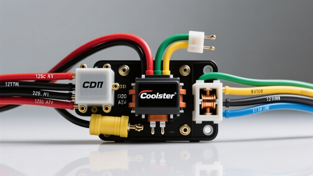
Understanding the Coolster 125cc ATV Wiring Diagram
If you are stepping into the world of import off-road vehicles, the Coolster 125cc ATV wiring diagram can initially look like a bowl of colorful spaghetti. Models like the Coolster 3125X or 3050C are fantastic, reliable entry-level quads, but their electrical systems often intimidate new owners. The good news? These machines utilize a highly standardized, beginner-friendly electrical architecture derived from classic Honda designs. By understanding a few core fundamentals, you can trace circuits, diagnose no-spark conditions, and confidently install aftermarket accessories without frying your harness.
This guide breaks down the essential circuits of the Coolster 125cc engine, focusing on the stator, regulator/rectifier, and the Capacitor Discharge Ignition (CDI) system. We will cover exact wire color codes, American Wire Gauge (AWG) requirements, and real-world troubleshooting steps to get you back on the trails.
The Heritage of Import Wire Color Codes
Before diving into the specific diagram, it is crucial to understand that most Chinese-manufactured 125cc horizontal engines (often clones of the Honda CRF or ATC engines) use a standardized color-coding system. Recognizing these colors allows you to trace circuits even if your physical wiring harness has faded or been modified by a previous owner.
- Green: Universal Ground (Chassis and Engine Block)
- Black/Red or Solid Black: 12V DC Power from Battery or Ignition Switch
- Yellow: AC Voltage from Stator Lighting Coil (Headlights)
- White or Pink: AC Voltage from Stator Charging Coil (to Regulator)
- Blue/White: Trigger/Pulse Signal from Stator to CDI
- Black/White: Engine Kill Switch Circuit
- Black/Yellow: High-Voltage Feed from CDI to Ignition Coil
Core Component 1: The Stator and Regulator/Rectifier
The stator is located behind the left-side engine cover and acts as your ATV's alternator. It generates raw Alternating Current (AC) as the magnetic flywheel spins over its copper windings. The Coolster 125cc typically uses a dual-coil stator: one winding for ignition/charging and one for lighting.
Because your battery and DC accessories require Direct Current (DC), the raw AC power must pass through the Regulator/Rectifier. This small, finned aluminum box (usually mounted near the front fenders for airflow) converts AC to DC and caps the voltage at roughly 14.2V to prevent overcharging the 12V battery.
Regulator/Rectifier Pinout (Standard 4-Pin)
- Yellow Wire: AC Input from Stator Lighting Coil
- White Wire: AC Input from Stator Charging Coil
- Red Wire: DC Output to Battery (12V+)
- Green Wire: Ground
Expert Tip: A common failure point on Coolster quads is the 4-pin plastic connector leading into the regulator. Due to engine heat and vibration, the brass terminals can corrode or melt. If your battery is constantly dying but the stator outputs 28V+ AC on a multimeter, inspect this plug for heat damage.
Core Component 2: The 5-Pin DC CDI Pinout
The CDI (Capacitor Discharge Ignition) module is the brain of your ignition system. Most electric-start Coolster 125cc models use a 5-pin DC CDI. Unlike older AC CDIs that generate their own spark power from a dedicated stator coil, a DC CDI relies on the 12V battery to charge its internal capacitor, resulting in a stronger, more consistent spark at low RPMs.
| Pin Number | Wire Color | Function / Destination | Voltage / Signal Type |
|---|---|---|---|
| 1 | Black/Red (or Black) | 12V DC Power Supply | 12V DC (Key ON) |
| 2 | Blue/White | Pulse/Trigger Pickup | 0.5V - 2V AC Pulse |
| 3 | Green | System Ground | 0V (Continuity to Block) |
| 4 | Black/White | Kill Switch / Lanyard | Grounded to Kill |
| 5 | Black/Yellow | Output to Ignition Coil | 200V - 400V DC Spike |
Understanding the Kill Switch Logic
Beginners often confuse automotive ignition logic with ATV logic. In a car, turning the key 'off' cuts power to the ignition system. On your Coolster 125cc, the kill switch and tether lanyard operate on a normally-open ground circuit. Pin 4 (Black/White) monitors for a ground connection. When you press the kill switch or pull the tether, you are physically connecting the Black/White wire to the Green ground wire. This instantly shorts the CDI's internal capacitor, killing the spark. If your ATV has zero spark, always check that the Black/White wire is not accidentally pinched and grounding out against the frame.
Wire Gauge Specifications and SAE Standards
When repairing or extending your Coolster's wiring harness, using the correct wire thickness is critical to prevent voltage drops and electrical fires. According to SAE International's J1128 standard for low-tension primary cable, wire gauge must be matched to the circuit's maximum amperage and length.
- 10 AWG to 12 AWG: Used exclusively for the battery main ground, battery to starter solenoid, and solenoid to starter motor. These circuits pull 50 to 120 amps during cranking.
- 14 AWG to 16 AWG: Main harness power feeds, headlight power, and winch control relay feeds (10-15 amp circuits).
- 18 AWG to 20 AWG: Stator signal wires, CDI trigger wires, and tail light circuits (under 5 amps). Do not use wire thicker than 18 AWG for the CDI plug, as it will not seat properly into the micro-pins and can cause a loose connection.
Beginner Troubleshooting: The 'No-Spark' Diagnostic Tree
The most common issue on any 125cc ATV is a 'cranks but won't start' scenario. Before replacing parts, follow this logical diagnostic sequence. As outlined in standard Haynes ignition testing procedures, you must verify the system step-by-step from the source to the spark plug.
Step 1: Verify the Kill Circuit
Disconnect the main harness plug from the CDI. Set your multimeter to continuity (the beep setting). Place one probe on Pin 4 (Black/White) and the other on the engine block. With the key ON and the kill switch in the 'RUN' position, there should be no continuity (OL). If the meter beeps, your kill switch, tether lanyard, or ignition cylinder is shorted to ground.
Step 2: Test the Stator Trigger Coil
If the kill circuit is clear, check the trigger signal. Set your multimeter to AC Voltage (20V scale). Back-probe Pin 2 (Blue/White) at the CDI harness. Have a helper kick-start or crank the engine. You should see a voltage spike between 0.5V and 2.5V AC. If you read 0V, your stator trigger coil or the flyway air-gap is faulty.
Step 3: Test the Ignition Coil Primary Winding
If the CDI is receiving power and a trigger signal, the issue may lie in the ignition coil itself. Remove the spark plug cap and set your multimeter to Ohms/Resistance (200 scale). Measure between the coil's primary wire terminal (usually a spade connector) and the coil mounting bracket (ground). A healthy primary winding will read between 0.3 and 1.0 Ohms. An open circuit (OL) means the internal copper windings are broken, requiring a coil replacement.
Essential Wiring Tools and Best Practices
Working on off-road vehicles exposes wiring to mud, water, and extreme vibrations. Standard electrical tape is a beginner's trap; it unrolls when exposed to engine heat and traps moisture, leading to green corrosion. To ensure your repairs last, adopt these professional habits:
- Ditch the Twist-and-Tape: Never twist wires together and wrap them in tape. Use adhesive-lined marine heat shrink with a solder seal core, or use a high-quality ratcheting wire crimper with nylon-insulated butt connectors.
- Dielectric Grease is Mandatory: Apply a dab of silicone dielectric grease to every electrical connector, especially the CDI plug, stator plug, and spark plug boot. This displaces water and prevents the brass terminals from oxidizing.
- Engine Block Grounds: The CDI and ignition coil rely on the engine block for grounding. If the engine mounting bolts are loose or painted, the circuit will fail. Clean the grounding surface with sandpaper and torque the engine case ground bolts to 8-10 Nm to ensure bare metal contact without stripping the soft cast aluminum.
By mastering these fundamentals, the Coolster 125cc ATV wiring diagram transforms from a confusing web into a logical roadmap. Whether you are upgrading to an LED light bar or diagnosing a dead coil, understanding the flow of power and the logic of the ground circuits will keep your quad running reliably for years to come.