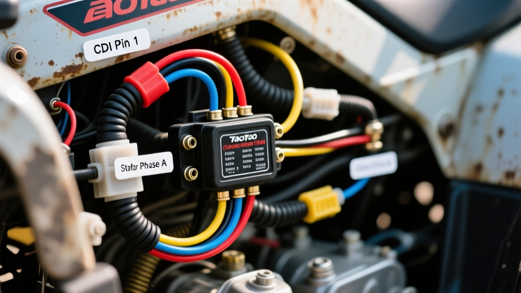
Decoding the Taotao 110cc Electrical Architecture
When troubleshooting or modifying a Taotao, Roketa, or Coolster quad, understanding the taotao electric start chinese 110cc atv wiring diagram is critical. These vehicles universally rely on the 152FMH horizontal single-cylinder engine platform. Unlike modern Japanese or American ATVs that utilize complex ECU-controlled multiplexed harnesses, the Chinese 110cc architecture uses a raw, analog, point-to-point wiring system. While this makes repairs accessible, it also means wire color codes can occasionally vary between manufacturing batches. However, the core circuit logic remains strictly standardized.
In this complete walkthrough, we will trace the electrical current from the stator magneto through the regulator/rectifier, map the CDI ignition pinouts, and dissect the electric start solenoid circuit. All wire gauge recommendations adhere to SAE J1128 low-tension automotive wire standards to ensure fire-safe, reliable operation in high-vibration off-road environments.
The Ignition Core: Stator and CDI Module
The heartbeat of the 110cc ATV is its AC magneto stator. Unlike DC-ignition systems that rely on the 12V battery to fire the coil, the Taotao 110cc uses an AC-CDI (Capacitor Discharge Ignition). This means the engine will generate spark even if the battery is completely dead or disconnected, provided the stator is functional.
4-Pin AC CDI Pinout Configuration
Most Taotao 110cc models utilize a 4-pin CDI module housed in a black epoxy block. The connector is a standard 4-way JST-style waterproof plug. Here is the exact pin mapping:
- Pin 1 (Black/Yellow): Ignition Coil Positive. Carries the high-voltage discharge (up to 400V) to the primary side of the ignition coil.
- Pin 2 (White): Stator AC Power Input. Receives raw, unregulated alternating current (typically 30V-50V AC) directly from the stator's dedicated ignition winding.
- Pin 3 (Green): Chassis Ground. Must have less than 0.5 ohms of resistance to the engine block.
- Pin 4 (Blue/White): Pickup/Trigger Signal. Receives the magnetic pulse from the flywheel sensor, telling the CDI exactly when to dump the capacitor charge.
Expert Note: The Black/White wire often found on the harness is the engine kill switch circuit. It splices into the Black/Yellow or operates as a secondary ground interrupt. When the handlebar kill switch is pressed, this wire is grounded to the engine block, shorting the CDI and killing the spark.
Stator Output and Regulator/Rectifier Routing
The stator on a 110cc ATV typically outputs four wires. Misrouting these wires during an engine swap or harness rebuild is the number one cause of blown regulators and dead batteries. According to the FamilyGoKarts technical archives, the standard 4-wire stator configuration is as follows:
| Wire Color | AWG Size | Function | Multimeter Test Spec (Engine Cranking) |
|---|---|---|---|
| White | 18 AWG | CDI AC Power (Unregulated) | 15V - 50V AC |
| Yellow | 16 AWG | Lighting / Regulator AC Input | 12V - 30V AC (RPM dependent) |
| Blue/White | 20 AWG | Pickup Coil Trigger Signal | 0.2V - 2.0V AC pulse |
| Green | 16 AWG | Stator Ground | 0.0 Ohms to Engine Block |
The 4-Pin Regulator/Rectifier
The regulator/rectifier converts the Yellow wire's AC output into 13.8V - 14.4V DC to charge the 12V battery and run the lighting circuit. Critical Warning: Never connect the White stator wire to the regulator. The White wire is strictly for the CDI. Feeding the White wire into the regulator will over-volt the DC system, instantly boiling your battery acid and blowing every 12V bulb on the ATV.
Electric Start Circuit: Solenoid and Interlocks
The electric start system on a Taotao 110cc is a heavy-current, ground-switched relay circuit. Because the starter motor draws between 40 and 80 amps under load, the main power cables must be a minimum of 10 AWG stranded copper wire. Using 12 AWG or smaller will result in severe voltage drop, causing the starter to spin sluggishly and the solenoid contacts to weld together from arcing.
Starter Relay Trigger Logic
The starter solenoid (relay) has two large threaded terminals and a 2-pin spade trigger connector.
- Large Terminal 1 (Red, 10 AWG): Direct connection to the battery positive terminal via a 15A or 20A main inline fuse.
- Large Terminal 2 (Black, 10 AWG): Direct connection to the starter motor positive post.
- Trigger Pin 1 (Yellow/Red, 18 AWG): Receives 12V positive from the ignition switch when turned to the "ON" position, routed through the handlebar starter button.
- Trigger Pin 2 (Green, 18 AWG): Ground path. This wire routes to the chassis ground, but it is usually intercepted by the Brake Safety Interlock Switch.
How it works: When you turn the key ON and press the starter button, 12V travels down the Yellow/Red wire to the relay coil. However, the relay will not engage unless the Green wire has a path to ground. On Taotao ATVs, you must pull the brake lever to close the brake light switch, completing the ground circuit and allowing the solenoid to click and engage the starter motor.
Common Failure Modes & Multimeter Diagnostics
Chinese ATV wiring harnesses are notorious for poor terminal crimps and lack of dielectric grease, leading to galvanic corrosion. Here is how to diagnose the three most common electrical failures using a standard digital multimeter (DMM).
1. Engine Cranks But Has No Spark
If the starter spins but the engine won't fire, bypass the harness and test the ignition components directly.
- Test the Pickup Coil: Disconnect the stator plug. Set your DMM to Ohms (Ω). Measure between the Blue/White wire and the Green wire. A healthy pickup coil should read between 110 and 180 ohms. If it reads infinite (OL), the internal winding is broken.
- Test the Ignition Coil Primary: Measure resistance between the Black/Yellow wire (coil +) and the engine block. It should read 0.5 to 1.5 ohms.
- Test the Ignition Coil Secondary: Remove the spark plug cap. Measure from the spark plug wire core to the engine block. Spec is 5,000 to 15,000 ohms (5k-15k). If it's out of spec, replace the coil.
2. Battery Overcharging (Boiling Acid)
If your battery is bulging or the headlight blows out at high RPM, your regulator is failing to shunt excess AC voltage to ground. In 90% of Taotao 110cc cases, this is not a bad regulator. It is a bad ground on the Green wire. The regulator requires a flawless ground to bleed off excess voltage. Sand the grounding bolt on the frame, apply dielectric grease, and ensure the Green wire has absolute continuity to the battery negative terminal.
3. Starter Relay Clicks But Starter Won't Spin
A rapid clicking sound indicates the relay trigger circuit has enough voltage to pull the internal electromagnet, but the heavy 10 AWG circuit is suffering from massive voltage drop. Check the main 15A inline fuse holder near the battery. These cheap plastic fuse holders often melt internally, creating high resistance. Bypass the factory fuse holder and install a marine-grade waterproof circuit breaker or a sealed ANL fuse block to guarantee uninterrupted current flow to the starter solenoid.
The AC to DC Headlight Conversion
From the factory, the Taotao 110cc headlight is wired directly to the Yellow stator wire via the lighting coil. This means the headlight runs on raw AC voltage and dims at idle. To fix this, advanced mechanics perform an AC-to-DC conversion. This involves disconnecting the Yellow wire from the headlight switch, routing the headlight switch to a 12V DC source (like the Red wire off the ignition switch), and ensuring the 55W headlight bulb is swapped to a DC-rated LED or halogen. This modification requires upgrading the stator lighting coil ground and verifying the regulator can handle the increased DC load without overheating.