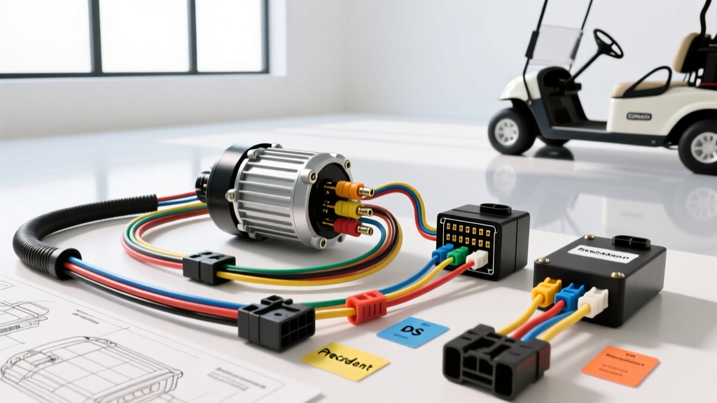
Understanding the SepEx Club Car Electric Motor Architecture
When tackling a wiring overhaul or diagnostic routine on a modern golf cart, understanding the underlying architecture is critical. Unlike older Series-wound setups that relied on mechanical V-Glide throttles and resistor coils, the modern club car electric motor ecosystem is dominated by the IQ and IQ+ systems utilizing Separately Excited (SepEx) motors. This SepEx design separates the armature and field windings, allowing the controller to manipulate the field current independently. This independent manipulation is what enables advanced features like regenerative braking, rollaway protection, and precise speed mapping.
In this complete wiring diagram walkthrough, we will dissect the electrical pathways from the 48V battery pack through the main solenoid, into the IQ controller, and finally to the motor terminals. Whether you are troubleshooting a dead cart, upgrading to an Alltrax high-performance controller, or simply tracing a parasitic draw, this guide provides the exact pinouts, AWG requirements, and color codes you need.
High-Current Battery & Solenoid Routing
The foundation of any high-torque electric drivetrain is the main power delivery network. For a standard 48V Club Car (comprising six 8V deep-cycle batteries or four 12V AGM/Lithium cells), voltage drop across the main cables is the primary enemy of performance and efficiency.
Cable Sizing and Termination Standards
- Main Battery Cables: Use 4 AWG or 2 AWG flexible welding cable. According to the SAE J1128 standard for low-tension primary cables, flexible stranding is mandatory to withstand the high-frequency vibrations of the cart chassis without suffering from copper fatigue and internal wire breakage.
- Motor Leads: 6 AWG high-strand-count silicone or EPDM-insulated wire is required to handle the 300+ amp peak draws during heavy acceleration or hill climbs.
- Terminations: Never solder high-current golf cart lugs. Solder can melt under extreme amperage loads, causing the terminal to slip. Always use a hydraulic crimper for 5/16-inch ring terminals, followed by a heat-shrink seal with internal adhesive to prevent battery acid corrosion.
- Torque Specifications: Motor studs and battery terminals should be torqued to exactly 120-150 in-lbs. Overtightening will snap the motor stud; undertightening will cause micro-arcing and melt the terminal.
The Main Solenoid and Pre-Charge Circuit
The heavy-duty 48V solenoid acts as the primary contactor. However, slamming 48V directly into a controller with massive internal capacitors would cause a destructive inrush current, welding the solenoid contacts shut. To prevent this, a pre-charge resistor (typically 250-ohm, 10-watt ceramic) or a pre-charge diode is wired across the large solenoid terminals. This allows a small trickle of current to charge the controller capacitors before the main solenoid contacts close.
IQ Controller Pinout & Signal Wiring Walkthrough
The brain of the club car electric motor system is the motor speed controller. The factory IQ controller utilizes a 16-pin harness connector for low-voltage logic signals, throttle inputs, and directional switching. Below is the definitive pinout reference for the standard IQ harness.
| Pin | Function | Wire Color | AWG | Diagnostic Notes |
|---|---|---|---|---|
| 1 | B+ (Key Switch Power) | Red | 14 | Should read 48V-52V when key is ON and Tow/Run is in RUN. |
| 2 | B- (Logic Ground) | Black | 14 | Must have continuity to the main battery negative pack terminal. |
| 3 | Throttle High (5V Ref) | White | 18 | Outputs 5.0V from controller to MCOR/ITS sensor. |
| 4 | Throttle Wiper (Signal) | Green | 18 | Variable return voltage (0.8V resting to 3.2V full throttle). |
| 5 | Throttle Low (Sensor Gnd) | Black | 18 | Sensor ground reference. |
| 6 | Forward Input | Blue | 14 | Receives 48V when F/R switch is in Forward. |
| 7 | Reverse Input | Yellow | 14 | Receives 48V when F/R switch is in Reverse. |
| 8 | Reverse Buzzer Trigger | Gray | 18 | Sends ground signal to activate the backup alarm. |
| 11 | Tow/Run Switch Input | Purple | 14 | 48V present in RUN mode; 0V in TOW mode. |
Note: Pins 9, 10, 12, 13, 14, 15, and 16 are typically reserved for optional accessories, serial communication (OBC), or specific regenerative braking mapping in later IQ+ and Precedent models.
Throttle Input: MCOR vs. ITS Diagnostics
Early Club Car IQ models (1996-2001) used an Inductive Throttle Sensor (ITS), which relied on a moving ferrite core inside a coil to change inductance. These are notorious for failing due to moisture ingress and dirt accumulation. From 2002 onward, Club Car transitioned to the MCOR (Motor Controller Output Regulator), and later the MCOR4, which is a hall-effect or potentiometer-based unit.
Testing the Throttle Signal
- Set your digital multimeter to DC Voltage.
- Backprobe Pin 3 (White) and Pin 5 (Black) at the controller harness. With the key ON, you must see exactly 5.0V (+/- 0.1V). If this is missing, the controller's internal 5V voltage regulator has failed.
- Backprobe Pin 4 (Green) and Pin 5 (Black). With the pedal at rest, you should read between 0.7V and 0.9V. This is your 'dead zone' to prevent creep.
- Slowly depress the accelerator. The voltage should climb linearly to approximately 3.2V to 3.5V at full stroke. Any sudden drops to 0V or spikes to 5V indicate a dead spot in the potentiometer track, requiring immediate MCOR replacement.
Forward/Reverse Switch & Microswitch Continuity
The F/R switch on a Club Car is not just a simple mechanical toggle; it is a complex rotary assembly that routes high-voltage logic signals to the controller while simultaneously actuating microswitches for the reverse buzzer and solenoid coil activation.
A common failure mode occurs when the cart moves in Forward but acts dead in Reverse. This is rarely a motor issue and almost always a failed microswitch or a burnt contact inside the F/R rotary housing. To diagnose:
- Disconnect the 4-pin harness at the F/R switch.
- Use a multimeter in continuity mode.
- In Forward, Pins 1 and 2 should show continuity (closing the solenoid coil ground path).
- In Reverse, Pins 3 and 4 should show continuity, while a separate internal cam triggers the reverse buzzer microswitch.
- If the mechanical cam is worn, the microswitch will not fully depress, leaving the controller blind to the directional input and triggering an HPD (High Pedal Disable) or directional fault.
Motor Terminal Mapping (A1, A2, F1, F2)
The SepEx club car electric motor features four primary high-current terminals. Understanding how the controller manipulates these is crucial for wiring aftermarket controllers or diagnosing field-weakening issues.
- A1 (Armature 1): Connected to the Controller's M- (Motor Negative) terminal via a 6 AWG Green wire.
- A2 (Armature 2): Connected to the main solenoid and Controller's B+ (Motor Positive) via a 6 AWG Red wire.
- F1 (Field 1): Connected to the Controller's F1 terminal via a 6 AWG Blue wire.
- F2 (Field 2): Connected to the Controller's F2 terminal via a 6 AWG Yellow wire.
The Science of Field Weakening
To achieve top speeds beyond the factory 14-15 MPH limit, performance controllers utilize 'field weakening.' By intentionally reducing the current flowing through the F1 and F2 field windings while maintaining maximum current through the A1/A2 armature, the motor's back-EMF is lowered, allowing the armature to spin at higher RPMs. If your F1/F2 wiring is undersized (e.g., using 10 AWG instead of 6 AWG), the voltage drop will inadvertently weaken the field under load, causing the motor to over-rev, overheat, and potentially throw a centrifugal mechanical failure.
Real-World Failure Modes & Flash Code Diagnostics
The factory Club Car IQ controller features a built-in LED diagnostic tool located on the side of the aluminum housing. By turning the key on and placing the Tow/Run switch in RUN, the controller will flash a sequence of blinks to indicate specific wiring or component faults. Consult Buggies Unlimited technical archives for comprehensive OEM replacement part numbers when these codes appear.
Common IQ Flash Codes
- 2 Blinks (HPD - High Pedal Disable): The controller detected throttle input (voltage above 1.0V on Pin 4) the exact millisecond the key was turned on. This is a safety feature to prevent the cart from launching if the pedal is stuck. Fix: Check for a binding throttle cable or a failed MCOR return spring.
- 3 Blinks (Directional Fault): The controller sees 48V on both the Forward (Pin 6) and Reverse (Pin 7) inputs simultaneously, or sees neither. Fix: Inspect the F/R switch for melted internal contacts or water intrusion causing a short across the harness.
- 4 Blinks (Solenoid Fault): The controller is sending the ground signal to close the solenoid, but does not see the main pack voltage appear on the motor side of the solenoid. Fix: Test the 250-ohm pre-charge resistor. If the resistor is blown, the capacitors never charge, and the heavy contacts will not pull in.
- 5 Blinks (Throttle Fault): The wiper signal (Pin 4) is reading outside the acceptable 0.5V to 4.5V window. Fix: Check for chafed wires in the steering column harness where the wires bend near the MCOR.
Final Routing and Loom Protection
When reassembling the wiring harness, never zip-tie low-voltage signal wires (18 AWG throttle and logic lines) directly to the high-current 4 AWG battery cables. The electromagnetic interference (EMI) generated by 300+ amps of DC current pulsing through the main cables can induce 'ghost voltages' in the signal wires, causing erratic throttle behavior or phantom regenerative braking. Always route signal wires through a separate split-loom conduit and maintain at least a 2-inch physical separation from the main power bus. Proper adherence to these wiring standards ensures your Club Car electric motor system operates safely, efficiently, and reliably for years to come.