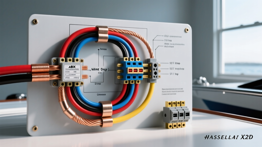
The Myth of the "Simple" Marine Electrical System
When boaters begin planning their vessel's electrical layout, they almost universally start by searching for a simple basic boat wiring diagram. The logic seems sound: connect a battery to a switch, run a positive wire to a load, and ground it back to the battery. However, applying automotive or household logic to a marine environment is a recipe for catastrophic failure. Saltwater, constant vibration, high humidity, and galvanic reactions turn a "simple" circuit into a severe fire hazard or a source of stray current corrosion that can sink a vessel.
As an electrical systems specialist, I frequently dismantle vessels where a basic diagram was executed with automotive wire and standard butt connectors. Within two years, the copper turns black from electrolytic corrosion, resistance spikes, and voltage-sensitive navigation electronics fail. To build a reliable system, we must take that simple basic boat wiring diagram and elevate it using the rigorous ABYC E-11 AC & DC Electrical Systems on Boats standards.
Deconstructing the Core Topology
A proper marine DC topology is never a direct point-to-point wiring web. It relies on centralized distribution to ensure manageable overcurrent protection and clean grounding. The foundational layout of an advanced basic diagram includes:
- Battery Bank & Main Disconnect: A heavy-duty battery switch (e.g., Blue Sea Systems 9001e) rated for continuous amperage (typically 300A+) must sit on the positive trunk line.
- Positive Distribution Busbar: Fused or breaker-protected feeds branch out from a tin-plated copper busbar, not directly from the battery terminal.
- Negative Distribution Busbar: All DC grounds must return to a dedicated, insulated negative busbar. The battery negative is then connected to this busbar via a single, heavy-gauge trunk cable. Grounding loads directly to the battery terminal creates an unmanageable "rat's nest" that traps moisture and promotes corrosion.
- Shunt Integration: A precision 500A/50mV shunt is installed on the negative trunk line *between* the negative busbar and the battery. This is the only path to ground, allowing a battery monitor to track all DC current flow accurately.
Conductor Selection: The ABYC Mandate
The most critical flaw in executing a simple basic boat wiring diagram is using standard automotive SAE J1128 wire. Marine environments require wire manufactured to UL 1426 / SAE J1128 marine specifications. Marine-grade wire utilizes 100% tinned, ASTM B172 copper strands to prevent oxidation from creeping inside the insulation jacket. Furthermore, the PVC insulation is rated for 105°C in dry locations and 75°C in wet engine spaces, and it resists oil, gasoline, and UV degradation.
Consider the strand count difference: a standard 16 AWG automotive wire contains roughly 26 strands. A 16 AWG Type 3 marine wire contains 65 ultra-fine strands, providing the flexibility required to withstand the constant harmonic vibration of a marine diesel or outboard engine without suffering work-hardening and copper fatigue.
ABYC & ANCOR Marine Wire Color Codes
Adhering to standardized color codes is non-negotiable for troubleshooting and safety. The ABYC dictates specific colors for DC circuits to prevent catastrophic miswiring.
| Wire Color | ABYC Designation | Common Marine Application |
|---|---|---|
| Red | Positive Ungrounded (DC+) | Main battery feeds, positive busbar jumpers, panel feeds. |
| Black or Yellow | DC Ground / Negative (DC-) | Battery negative, busbar returns, load grounds. (Yellow preferred to avoid confusion with AC Black). |
| Yellow/Red Stripe | Starting Motor Positive | Engine starter solenoid feeds, heavy cranking circuits. |
| Dark Blue | Navigation / Instrumentation | Running lights, depth sounders, GPS power feeds. |
| Light Blue | Accessories / Bilge | Automatic bilge pump switches, cabin blowers. |
| Orange | Distribution / Common Feed | Ignition switches, accessory distribution panels. |
Voltage Drop Calculations: The 3% Rule
A basic diagram assumes that if a wire fits the terminal, it will carry the current. In reality, wire length causes resistance, resulting in voltage drop. ABYC mandates a maximum 3% voltage drop for navigation lights, instrumentation, and electronics, and a 10% drop for non-critical loads like cabin lighting or bait pumps.
To calculate the required Circular Mils (CM) for your wire gauge, use the following formula:
CM = (2 × L × I × 10.75) / VD
- L = Total circuit length (Positive + Negative run in feet)
- I = Current draw in Amps
- 10.75 = Resistivity constant for copper at standard marine temperatures
- VD = Allowable Voltage Drop (e.g., 0.36V for a 3% drop on a 12V system)
Real-World Scenario: You are wiring a 5A LED navigation light located 30 feet from the panel. The total round-trip wire length is 60 feet. The allowable drop is 0.36V.
CM = (2 × 30 × 5 × 10.75) / 0.36 = 8,958 CM.
Checking the AWG chart, 16 AWG wire is 5,180 CM (too small, will cause >5% drop). 14 AWG is 8,250 CM (still slightly under). You must step up to 12 AWG (13,090 CM) to safely maintain the 3% threshold over that distance.
Overcurrent Protection & Terminal Execution
Every positive wire leaving a distribution bus must be protected by a fuse or breaker within 7 inches of the busbar (or 72 inches if enclosed in a continuous sheath). Sizing is based on the wire's ampacity, not just the load. If you run 14 AWG wire (rated for 35A in engine spaces) to a 10A bilge pump, you must fuse it at 15A to protect the wire from melting before the breaker trips.
Heat-Shrink Crimping Specifications
Solder is strictly prohibited for primary mechanical connections in marine environments by the ABYC. Solder is brittle and will fracture under engine vibration, and the flux traps moisture, accelerating corrosion. Instead, you must use adhesive-lined, marine-grade heat shrink terminals.
According to Marine How To's extensive testing on marine electrical terminations, a proper ratcheting crimp tool must be used. The adhesive lining melts during the heat-shrink process, creating a watertight seal that prevents capillary action from drawing saltwater into the copper strands. Pull-test requirements for these crimps are rigorous: a 12 AWG terminal must withstand 35 lbs of pull force, while a 10 AWG terminal must hold 50 lbs without the wire slipping from the barrel.
Real-World Troubleshooting: Stray Current & Galvanic Corrosion
Even with a perfect diagram, poor execution leads to stray current corrosion—the most destructive force on an aluminum outdrive or bronze propeller. If a positive wire rubs against an engine block or a bilge pump float switch leaks current into the bilge water, that current will seek a path back to the battery negative. It will travel through the water and exit via your underwater metals, taking chunks of your propeller with it.
Diagnostic Procedure:
- Disconnect the vessel's negative battery cable.
- Set a digital multimeter to the DC Amps setting (10A max).
- Place the multimeter in series between the negative battery post and the disconnected negative cable.
- Turn off all DC breakers and remove all fuses. The reading should be exactly 0.00A.
- If you detect current flow (even 0.05A), you have a parasitic draw or a short to the hull ground. Reinsert fuses one by one until the current spikes, isolating the faulty circuit.
By treating your simple basic boat wiring diagram not as a final blueprint, but as a foundational topology that requires strict adherence to ABYC wire sizing, color coding, and termination standards, you ensure your vessel remains safe, reliable, and free from the electrical gremlins that plague poorly wired boats.