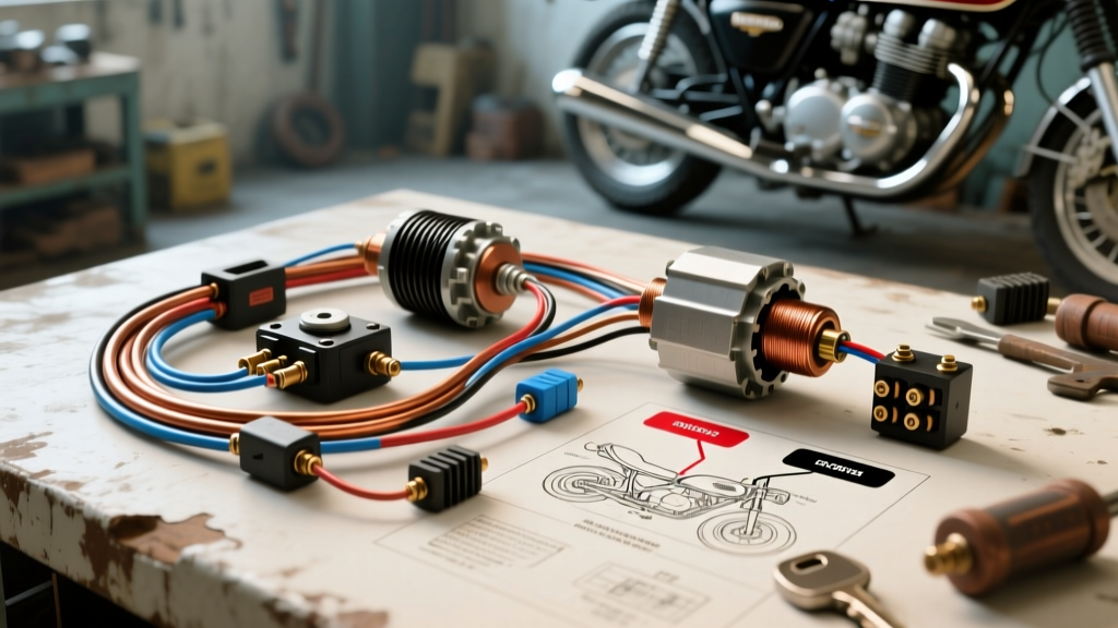
The Model Year Anomaly: 1969 CB450 vs. 1974 CB550
Any seasoned vintage Honda mechanic will immediately recognize an anomaly when searching for a 1969 Honda CB550 wiring diagram. Honda did not officially produce the CB550 Four until 1974, evolving it from the legendary 1971 CB500 Four. In 1969, Honda’s premier parallel-twin was the CB450 "Black Bomber," and their inline-four lineup had not yet debuted. However, this specific search query is incredibly common in the custom motorcycle community. Why? Because thousands of early 1970s CB500s have been bored out to 550cc using aftermarket piston kits, and many 1969 CB450s were mis-titled or swapped with early SOHC inline-four engines by previous owners. When you are building a cafe racer or brat-style custom from these early SOHC (Single Over Head Cam) engines, the electrical architecture remains fundamentally identical across the 1971-1978 CB500/CB550 lineage. This guide focuses on stripping away the brittle, 50-year-old OEM harness and fabricating a modernized, reliable custom loom for your inline-four project.
Wire Selection: Ditching OEM PVC for SAE TXL
The original Honda harness used PVC-insulated copper wire, which becomes brittle, cracks, and causes parasitic draws when exposed to decades of engine heat and UV radiation. For a modern upgrade, we strictly adhere to SAE J1128 standards by utilizing TXL (Thermoplastic Cross-Linked) wire. TXL wire features a thinner, highly abrasion-resistant insulation that can withstand continuous temperatures up to 125°C (257°F). Because the insulation is thinner and rated for higher heat, you can often step down one AWG size compared to standard PVC wire while maintaining the same current-carrying capacity, allowing for a much cleaner, tighter harness wrap.
| Circuit Type | OEM Honda AWG | Upgraded TXL AWG | Honda OEM Color Code |
|---|---|---|---|
| Main Battery Feed | 10 AWG | 12 AWG | Red |
| Ignition Switched (12V) | 14 AWG | 16 AWG | Black |
| Lighting Circuits | 16 AWG | 18 AWG | Blue / Brown |
| Sensors / Indicators | 18 AWG | 20 AWG | Light Green / Pink |
| Ground Circuits | 14 AWG | 16 AWG | Green |
Ignition Switch Pinout and Main Power Distribution
The OEM 4-pin ignition switch on the early SOHC fours is a frequent failure point. The internal copper contacts wear down, causing voltage drops that starve the ignition coils. When rewiring, retain the OEM switch but upgrade the connector to a sealed 4-pin Deutsch DT or Sumitomo weatherpack. The pinout remains critical for proper harness routing:
- Pin 1 (Red): Direct 12V+ from the battery via the main 15A inline fuse. This is always hot.
- Pin 2 (Black): Switched 12V+ output. This feeds the main harness junction, ignition coils, and lighting switches.
- Pin 3 (Brown): Switched 12V+ output dedicated to the tail light and instrument cluster illumination.
- Pin 4 (Blue): Parking light circuit (often deleted on cafe racer builds to simplify the loom).
By routing the Black and Brown wires through a modern 30A Bosch-style relay triggered by the ignition switch, you eliminate the high current draw passing through the fragile 50-year-old switch contacts, ensuring full battery voltage reaches your headlight and ignition system.
Charging System: Upgrading to a MOSFET Regulator
The early CB500 and CB550 charging systems utilize a permanent magnet alternator (PMA) paired with a crude mechanical shunt-style regulator/rectifier. This OEM setup is notorious for boiling batteries and frying stators. For your custom build, bypass the OEM rectifier entirely and install a modern Shindengen SH775 MOSFET regulator/rectifier. The stator outputs three Yellow AC wires. These must be connected directly to the three AC input terminals on the SH775 (phase order does not matter on a 3-phase PMA). The SH775 outputs a clean, regulated DC voltage. Connect the Red output wire to the battery side of your main fuse, and the Green wire to your main ground bus. This upgrade alone will increase the lifespan of your stator and provide a rock-solid 14.2V at idle, which is essential if you are running modern LED lighting or electronic fuel injection.
Ignition Wiring: Points to Electronic Conversion
If your project still utilizes the OEM mechanical points and condensers, you are losing spark energy and dealing with constant timing drift. Upgrading to an electronic ignition system like the Pamco or Dyna-S is mandatory for a reliable build. The OEM ignition coils are fed by a Black/White wire (12V switched) and grounded via the points using Blue and Yellow wires. When installing an electronic igniter, the Black/White wire still provides the 12V+ trigger, but the Blue and Yellow wires now route to the negative terminals of the igniter module, which handles the rapid ground-switching. Crucial Modification: You must completely remove the OEM point condensers from the harness. Leaving them in the circuit with an electronic igniter will cause severe voltage spikes that will instantly destroy the solid-state switching transistors in your new ignition module. Consult the SOHC4.net technical archives for specific air-gap measurements and magnetic pickup alignment procedures for your specific engine serial number.
Curing the 'Green Wire' Ground Syndrome
Ask any vintage Honda builder about their biggest electrical nightmare, and they will unanimously cite "Green Wire Syndrome." Honda’s OEM wiring diagram dictates that every single ground circuit is color-coded Green. Instead of running dedicated ground wires back to the battery, Honda relied on the motorcycle's frame, engine cases, and handlebars to complete the circuit, using the green wires merely as jumpers between bolted components. Over 50 years, engine vibration, powder coating, and corrosion create massive resistance in these ground paths, resulting in dim headlights, erratic neutral indicators, and weak spark. The ultimate modification is to abandon the frame-ground philosophy. Fabricate a centralized copper ground bus bar mounted under the fuel tank or seat cowl. Run dedicated 16 AWG Green TXL wires from every electrical component (headlight bucket, tail light, ignition coils, instrument cluster) directly back to this bus bar, and connect the bus bar to the battery negative terminal with a heavy 10 AWG cable. This star-ground topology guarantees zero voltage drop on the ground side of your circuits.
Headlight Bucket Simplification and Connectors
The OEM CB500/CB550 headlight bucket houses a massive, brittle multi-pin connector block that is a nightmare to troubleshoot. When building a custom harness, pull all switchgear wiring out of the headlight bucket and route it down the frame backbone to a centralized, sealed fuse box and relay block located under the seat. Use OEM Honda parts diagrams to verify the internal switch continuity for the high/low beam dimmer and turn signal canceling mechanisms before cutting any wires. By relocating the heavy current relays to the rear of the bike, you only need to run low-current trigger wires up the steering neck, drastically reducing the thickness of the harness where it needs to flex and bend. Finish all connections with adhesive-lined heat shrink and nylon braided sleeving for a factory-quality, moisture-proof loom that will easily outlast the next 50 years of riding.