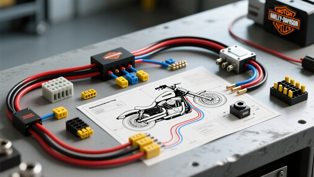
Introduction to Sportster 1200 Electrical Architecture
The Harley-Davidson Sportster 1200 is a cornerstone of American motorcycling, celebrated for its raw mechanical feel and extensive aftermarket support. However, integrating modern electronics—such as auxiliary LED driving lights, heated grips, or USB power hubs—requires a precise understanding of the motorcycle's electrical system. When querying search engines for 'sportster 1200 sportster free harley davidson wiring diagrams', riders often encounter fragmented, low-resolution schematics that lack the necessary pinout details for safe accessory integration. Relying on incomplete diagrams can lead to overloaded ignition switches, melted harness connectors, or parasitic battery drains.
This practical how-to guide bridges the gap between factory service manual schematics and real-world garage applications. We will walk through the exact methodology for reading Harley-Davidson wiring diagrams, identifying ignition-switched circuits, and executing a professional-grade relay installation using industry-standard wire gauges and connectors.
Decoding Free Harley-Davidson Wiring Diagrams
Harley-Davidson factory wiring diagrams follow a standardized color-coding and labeling system that remains remarkably consistent across model years, particularly from the 2004 to 2013 Sportster 1200 generations. Before cutting into any harness, you must understand the primary power distribution colors:
- Orange (O): Unswitched battery positive. This wire is live at all times and is typically fused directly at the battery or starter solenoid.
- Gray (Gr): Ignition-switched positive. This circuit only receives 12V when the ignition key is in the 'ON' position. It powers the instrument cluster, ignition module, and OEM accessories.
- Black (Bk): Primary chassis and component ground.
- White/Red (W/R): Often used for accessory feeds or specific sensor signals, such as the bank angle sensor.
When utilizing free Harley-Davidson wiring diagrams, always locate the specific 'Accessory Connector' (often a 4-pin Deutsch DT or Molex connector tucked beneath the seat or near the voltage regulator on 2004+ models). This connector provides a pre-fused, ignition-switched power source designed specifically for low-draw accessories like sissy bar LED lights. However, for high-draw components exceeding 5 amps, you must use this switched circuit merely as a trigger for a heavy-duty relay.
Pre-Installation: Tools, Materials, and Specifications
Professional automotive electrical work demands the right materials. The SAE J1128 Low Tension Primary Cable Standard dictates the thermal and chemical resistance requirements for wires routed near internal combustion engines. Standard hardware store wire will not withstand the vibration and heat of a Sportster 1200 V-Twin.
| Component / Circuit | Wire Gauge (AWG) | Wire Color Code | Connector / Terminal Type | Protection / Fusing |
|---|---|---|---|---|
| Main Battery Feed to Relay (Pin 30) | 10 AWG | Red (Primary Power) | 5/16" Ring Terminal | Inline MAXI Fuse (15A) |
| Relay to High-Draw Accessory (Pin 87) | 12 AWG | Blue (Load) | Deutsch DT / Metri-Pack 150 | Fuse rated to accessory draw |
| Ignition Trigger to Relay (Pin 86) | 18 AWG | Gray (OEM Harness Tap) | Posi-Tap or Solder/Seal | Tapped after OEM 10A fuse |
| Relay Ground (Pin 85) | 14 AWG | Black (Chassis Ground) | 1/4" Ring Terminal w/ Star Washer | Adhesive-lined heat shrink |
Step-by-Step: Tapping the Accessory Circuit via Relay
The ignition switch on a Sportster 1200 is not designed to handle the inrush current of heavy auxiliary lighting or heated gear. Bypassing the switch with a relay ensures longevity and prevents voltage drop to the critical Electronic Sequential Port Fuel Injection (ESPFI) system.
Step 1: Accessing the Main Harness and Battery Disconnect
Begin by removing the seat and the left side cover to expose the battery and main fuse block. Crucial Safety Step: Always disconnect the negative (black) battery cable first. On Harley-Davidson motorcycles, the main positive cable from the battery to the starter solenoid is often unfused. Dropping a wrench across the positive terminal and the frame will result in catastrophic arcing and melted harnesses. Once disconnected, isolate the negative cable with a shop towel to prevent accidental contact.
Step 2: Identifying and Tapping the Ignition-Switched Power
Locate the Gray wire exiting the ignition switch harness or the accessory pigtail under the seat. Using a digital multimeter set to DC Volts, reconnect the battery temporarily and turn the ignition to 'ON'. Probe the Gray wire; you should read between 12.2V and 12.8V. Turn the key off; the voltage should drop to 0V.
To tap this wire, strip back a 1/4-inch section of the Gray wire's insulation. Do not cut the wire entirely. Solder an 18 AWG trigger wire to the exposed copper, then seal the connection using dual-wall, adhesive-lined polyolefin heat shrink tubing. The adhesive lining melts and seals against the wire jacket, preventing moisture intrusion—a critical factor referenced in Electrosport Motorcycle Charging System Diagnostics for preventing harness corrosion.
Step 3: Routing, Splicing, and Relay Integration
Mount a standard Bosch-style 4-pin 12V relay in a dry location beneath the seat or inside the airbox cavity using a rubber isolation mount to dampen V-Twin vibration. Wire the relay according to the following pinout:
- Pin 30 (Power In): Connect a 10 AWG red wire directly to the positive battery terminal. Install an inline 15A blade fuse holder within 6 inches of the battery ring terminal.
- Pin 87 (Power Out): Connect a 12 AWG wire to your accessory's positive lead. Route this wire through a split-loom corrugated conduit to protect it from the exhaust headers.
- Pin 86 (Trigger In): Connect the 18 AWG wire you spliced into the OEM Gray ignition-switched circuit.
- Pin 85 (Ground): Connect a 14 AWG black wire to a clean, unpainted metal point on the frame.
Grounding Protocols and Torque Specifications
Because the Sportster 1200 features a rigid-mount engine (unlike the rubber-mounted Big Twins), the engine block and the frame share a common ground plane. However, poor grounding is the leading cause of flickering LEDs and erratic sensor behavior. When attaching your Pin 85 ground ring terminal, remove any existing bolt, clean the frame surface with a wire wheel down to bare metal, and install a stainless steel star washer between the ring terminal and the frame. This bites through microscopic oxidation layers. Torque the grounding bolt to the manufacturer's specification, typically 12-15 ft-lbs for 1/4" hardware, and coat the terminal in dielectric grease to prevent future galvanic corrosion.
When reattaching the battery cables, always connect the positive (red) cable first, followed by the negative (black) cable. Torque the battery terminal bolts to 70-100 in-lbs (8-11 Nm). Overtightening can strip the soft lead threads of the battery posts, while undertightening will cause high-resistance arcing during engine cranking.
Troubleshooting Common Voltage Drop Issues
If your newly installed accessory fails to operate, or operates dimly, avoid immediately blaming the component. Perform a systematic voltage drop test. According to Delphi Metri-Pack Connector Specifications, a healthy connection should exhibit less than a 0.1V drop across any single connector or splice.
- Symptom: Relay clicks, but accessory receives only 9V.
- Cause: Undersized wire on Pin 87 or a corroded inline fuse holder.
- Fix: Upgrade the load wire to 10 AWG and replace cheap stamped-brass fuse holders with marine-grade tin-plated copper holders.
- Symptom: Accessory stays on after the key is removed.
- Cause: The trigger wire was mistakenly tapped into an Orange (constant hot) wire instead of the Gray (switched) wire, or the relay is internally fused due to heat damage.
- Fix: Verify the trigger source with a multimeter and replace the relay if the internal coil has shorted.
By combining accurate interpretation of free Harley-Davidson wiring diagrams with rigorous SAE-standard installation practices, you ensure that your Sportster 1200's electrical system remains reliable, safe, and ready for the open road.