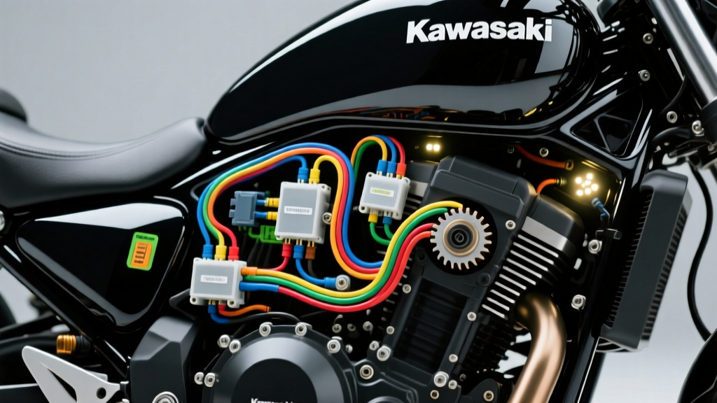
Understanding the VN1500 OEM Electrical Architecture
When embarking on an upgrade or modification project for your Kawasaki Vulcan 1500 (VN1500), relying on guesswork is a recipe for electrical gremlins, blown fuses, or worse, a stator fire. The VN1500 platform—spanning the Classic, Nomad, Drifter, and Mean Streak—features a robust but aging electrical system. Whether you are installing auxiliary LED driving lights, upgrading to a modern MOSFET regulator/rectifier, or swapping handlebars, a precise Kawasaki Vulcan 1500 wiring diagram is your most critical tool. This guide dives deep into the technical specifications, wire color codes, and relay logic required to execute custom motorcycle modifications safely and reliably.
The Kawasaki Vulcan 1500 utilizes a 12-volt, negative-ground electrical system driven by a 3-phase, permanent-magnet stator. From the factory, the stator outputs raw AC voltage, which is converted to DC by a shunt-style regulator/rectifier (R/R). The main harness routes through the steering neck and splits into sub-harnesses for the headlight bucket, instrument cluster, and rear fender.
Before cutting or splicing any wires, you must understand the Kawasaki color-code standard. Unlike automotive applications where wire colors vary wildly by year, Kawasaki maintains strict consistency:
- Red: Unswitched main battery power (Hot at all times)
- Black: Main chassis ground
- Brown: Ignition-switched power (Hot only when the key is ON)
- Green: Left turn signal circuit
- Gray: Right turn signal circuit
- Yellow/Red & Yellow/Green: Headlight high/low beam circuits
When referencing your Kawasaki Vulcan 1500 wiring diagram, always verify these colors with a digital multimeter (DMM). Decades of heat cycling and previous owner modifications can cause wire insulation to fade or become brittle.
Project 1: Upgrading the Stator and Regulator/Rectifier
The most common failure point on the VN1500 is the OEM shunt-style regulator/rectifier. Because it bleeds excess voltage as heat, it frequently overheats, leading to melted connectors and a dead battery. Upgrading to a Series-type or MOSFET R/R is a mandatory modification for any Vulcan 1500 touring build.
Stator Connector Elimination
The factory 3-pin rubber connector connecting the stator to the main harness is a known resistance bottleneck. According to ElectroSport Industries, resistance at this plug generates excess heat, eventually melting the plastic housing and causing a phase short.
The Fix: Cut the OEM 3-pin connector out entirely. The stator outputs three identical wires (typically Yellow or Black/Yellow). Extend these using 12 AWG high-strand silicone wire, which offers superior flexibility and heat resistance compared to standard PVC wire. Solder the connections using rosin-core solder, then seal them with dual-wall, adhesive-lined heat shrink tubing. This creates a waterproof, vibration-proof seal that meets SAE J1128 durability standards for primary cable.
R/R Power and Ground Upgrades
Do not rely on the OEM 16 AWG ground wire for your new R/R. Fabricate a new ground lead using 10 AWG wire, terminating it directly to the engine block or a clean, unpainted chassis bolt. The positive output (Red wire) should also be upgraded to 10 AWG and routed directly to the positive battery terminal via a 30A inline MAXI fuse.
Project 2: Auxiliary LED Lighting Installation via Relay
Adding auxiliary LED driving lights is a popular Nomad and Classic touring upgrade. However, the VN1500 stator produces roughly 380 watts at 5,000 RPM, and marginal output at idle. Tapping high-draw accessories directly into the OEM headlight or accessory plug will overload the circuit and melt the ignition switch contacts.
Designing the Relay Circuit
To protect the OEM Kawasaki Vulcan 1500 wiring diagram pathways, you must use a standard Bosch-style 4-pin 12V relay. The relay acts as a heavy-duty switch, allowing a low-amperage trigger signal to control a high-amperage direct battery circuit.
- Pin 30 (Power In): Run 12 AWG red wire from the positive battery terminal. Install a 15A ATO blade fuse within 6 inches of the battery post.
- Pin 87 (Power Out): Run 14 AWG red wire from the relay to your LED light harness. Split to the individual lights using a sealed Deutsch DT 2-way connector.
- Pin 85 (Ground): Terminate to a clean chassis ground using a ring terminal and star washer.
- Pin 86 (Trigger): This is where you tap the OEM harness. Use a Posi-Tap to connect to the OEM tail light wire (Red/White) or the dedicated accessory plug under the seat. This requires only 18 AWG wire, as it only carries the relay coil draw (approx. 150mA).
By using this relay logic, your auxiliary lights will only illuminate when the ignition is on and the tail light circuit is energized, completely isolating the heavy current draw from the Vulcan's fragile OEM switchgear.
Vulcan 1500 Main Harness Pinout Reference
When routing new harnesses or troubleshooting existing faults, referencing the main connector pinouts is essential. Below is the technical specification for the primary instrument cluster and headlight bucket connector found on 1996-2005 VN1500 models.
| Pin Number | Wire Color | Circuit Function | AWG Spec |
|---|---|---|---|
| 1 | Red | Main Battery Power (Unswitched) | 12 AWG |
| 2 | Black | Main Chassis Ground | 12 AWG |
| 3 | Brown | Ignition Switched (Meter Power) | 16 AWG |
| 4 | Yellow/Red | Headlight High Beam | 14 AWG |
| 5 | Yellow/Green | Headlight Low Beam | 14 AWG |
| 6 | Blue | High Beam Indicator Light | 18 AWG |
| 7 | Green | Left Turn Signal Power | 16 AWG |
| 8 | Gray | Right Turn Signal Power | 16 AWG |
Common VN1500 Wiring Faults & Troubleshooting
Even with a perfect modification plan, older Vulcan 1500s present unique troubleshooting scenarios. Here is a diagnostic decision tree for common electrical gremlins encountered during mod projects:
- Symptom: Battery drains overnight after installing LED accessories.
Cause: Parasitic draw from a relay wired directly to the battery instead of a switched trigger, or a cheap LED driver module lacking reverse-polarity protection.
Fix: Verify Pin 86 on your relay is connected to a switched Brown or Red/White wire, not a constant Red wire. Use a DMM in series with the negative battery terminal to measure parasitic draw; it should be under 2mA with the key off. - Symptom: Headlight flickers at idle, but brightens at 3,000 RPM.
Cause: The OEM stator is weak at low RPMs, or the new R/R ground has high resistance.
Fix: Perform a voltage drop test on the R/R ground wire. Place your DMM leads on the R/R casing and the negative battery post. A reading above 0.1V indicates a poor ground connection. Clean the mounting surface to bare metal and apply anti-seize to the bolt threads.
Professional Wiring Best Practices for the VN1500
To ensure your modifications survive the high-vibration environment of a V-twin cruiser, adhere to these professional standards:
- Never Use Twist Connectors: Wire nuts and twist-and-tape methods will vibrate loose and cause a short. Always use closed-barrel crimps or soldered joints.
- Dielectric Grease is Mandatory: Apply silicone dielectric grease to every OEM connector you unplug or mate. This prevents moisture ingress and galvanic corrosion, which is common on older Kawasaki harnesses.
- Split-Loom and Abrasion Protection: Where your new wiring harness rubs against the steel frame or passes through the steering neck, wrap the wires in nylon braided sleeving or Tesa tape. Friction against the frame will quickly wear through wire insulation, leading to a dead short.
- Verify with a Load Tester: After completing your stator upgrade or relay install, verify the system voltage at the battery terminals. According to Kawasaki OEM Service Documentation, the charging system should output between 13.5V and 14.5V at 3,000 RPM with the high beam on.
Final Thoughts
Modifying a Kawasaki Vulcan 1500 is a rewarding endeavor, but it demands respect for the electrical system's limits. By leveraging an accurate Kawasaki Vulcan 1500 wiring diagram, upgrading undersized stator wiring, and utilizing proper relay logic for auxiliary accessories, you ensure your cruiser remains reliable on the open road. Invest in high-quality wire, proper crimping tools, and heat shrink, and your custom electrical system will outlast the factory harness.