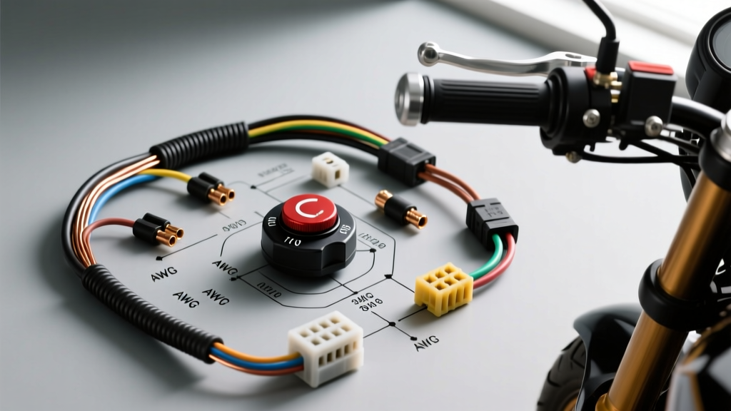
Decoding the Motorcycle Kill Switch Wiring Diagram
Understanding a motorcycle kill switch wiring diagram is the first step in diagnosing, repairing, or upgrading your bike's engine cutoff system. Unlike headlight or starter circuits that carry high amperage, the kill switch circuit is a low-current signal path. It typically interrupts the ignition coil's primary ground or sends a 12V logic signal to the CDI (Capacitor Discharge Ignition) or TCM (Transmission Control Module). Because the current draw is usually under 1 amp, the cost and tool requirements for repairing or fabricating this circuit are relatively low—provided you select the correct materials and avoid common amateur mistakes that lead to parasitic draws, voltage drops, or melted connectors.
From a cost-analysis perspective, the most expensive part of a kill switch repair isn't the switch itself; it is the collateral damage caused by using the wrong wire gauge, improper crimping tools, or failing to weatherproof the connections. This guide breaks down the exact tools, materials, and costs required to execute a flawless kill switch wiring project.
Essential Tool Requirements & Budget Breakdown
Before cutting into your main harness, you must assemble the right tools. Using improper crimpers or incorrect wire strippers is the leading cause of switch failure and intermittent stalling. Below is a cost and tool analysis categorized by DIY budget and professional-grade requirements.
| Tool Category | Budget Tier (DIY/Custom) | Professional Tier (OEM/Restoration) | Cost Difference |
|---|---|---|---|
| Wire Strippers | Standard automatic strippers ($15) | Knipex Micro-Stripper 12-18 AWG ($45) | +$30 |
| Crimpers | Generic ratcheting crimper ($20) | IWISS SN-28B for Sumitomo/Hirose ($45) | +$25 |
| Soldering | 60W Soldering Iron Kit ($25) | Weller WE1010NA Digital Station ($110) | +$85 |
| Testing | Basic Digital Multimeter ($15) | Fluke 115 True-RMS Multimeter ($180) | +$165 |
| Heat Shrink | Generic PVC tubing ($8) | 3M Polyolefin Dual-Wall Adhesive ($18) | +$10 |
Budget vs. Professional Tier Analysis
For a simple custom café racer or bobber build, the $83 budget tier is sufficient if you use high-quality vinyl-insulated bullet connectors and seal them with dielectric grease. However, if you are restoring a modern sportbike, working on a fuel-injected Harley-Davidson, or building a reliable touring harness, investing in the $303 professional tier is highly recommended. OEM-style connectors (like Sumitomo HM 090 series or Deutsch DT) resist moisture ingress and vibration-induced fretting, which are the primary killers of kill switch circuits on modern motorcycles.
Wire Gauge, Color Codes, and Connector Specs
According to SAE J1128 standards for low-tension primary cable, wire gauge selection must account for both current capacity and voltage drop over the length of the harness. For a kill switch circuit, 18 AWG TXL (Thermoplastic Cross-Linked) wire is the industry standard. It features a thin, abrasion-resistant insulation that allows for easier routing through tight handlebar switch housings compared to bulky THHN or standard primary wire. TXL wire costs approximately $0.15 to $0.25 per foot, making it a negligible expense in the overall project budget.
OEM Kill Switch Wire Color Reference Chart
When reading your specific motorcycle kill switch wiring diagram, identifying the correct signal wire is critical. Splicing into a 12V accessory wire instead of the CDI kill signal will result in a no-start condition or blown fuses. Below are the standard OEM color codes for major manufacturers:
| Manufacturer | Kill Signal Wire Color | Switch Logic Type | Common CDI/TCM Pin |
|---|---|---|---|
| Honda | Black with White Stripe (B/W) | Normally Open (Ground to Kill) | CDI Pin 4 or 6 |
| Yamaha | Red with White Stripe (R/W) | Normally Open (Ground to Kill) | TCI Pin 2 |
| Kawasaki | White with Red Stripe (W/R) | Normally Closed (Break to Kill) | Igniter Pin 5 |
| Harley-Davidson (Evo/Twin Cam) | Gray/Black or Pink (Varies by Year) | Normally Open (Ground to Kill) | Ignition Module Pin 2 |
Step-by-Step Cost-Effective Installation
To keep costs low and reliability high, follow this optimized installation sequence based on standard Haynes Motorcycle Electrical Manuals protocols:
- Disconnect the Battery: Always remove the negative terminal first to prevent accidental shorting of the main 12V feed while working near the handlebar controls.
- Trace the Diagram: Locate the kill switch on your diagram. Identify if it is a 2-wire (simple ground interrupt) or 3-wire (run/off/start integration) setup.
- Prepare the TXL Wire: Cut your 18 AWG TXL wire to length, adding 3 inches for service loops. Strip exactly 3mm of insulation using precision micro-strippers to avoid nicking the copper strands.
- Crimp and Solder: Insert the wire into a Sumitomo or OEM-style terminal. Crimp using the correct die (usually 1.5mm² or 22-18 AWG notch). For maximum reliability, apply a tiny amount of rosin-core solder to the wire-to-terminal crimp barrel, ensuring you do not wick solder up into the flexible wire.
- Weatherproofing: Slide a piece of 3M dual-wall adhesive heat shrink over the connection. Apply heat until the adhesive oozes slightly from the ends, creating a watertight seal. This $2 step prevents $200 CDI replacements caused by water intrusion.
- Test Before Routing: Before zip-tying the harness, use a multimeter in continuity mode to verify the switch opens and closes the circuit as dictated by the diagram.
Common Wiring Mistakes That Inflate Costs
When analyzing the true cost of a wiring project, you must factor in the financial impact of errors. Here are the most common mistakes that turn a $20 repair into a $500 nightmare:
- Using Solid Core Wire: Never use solid copper house wire. Motorcycle handlebars vibrate intensely, which will cause solid core wire to work-harden and snap inside the insulation within a few hundred miles. Always use stranded TXL or GXL wire.
- Ignoring Voltage Drop: While the kill switch carries minimal current, running excessively long, undersized wire (e.g., 22 AWG) over 6 feet can introduce resistance. If the CDI doesn't see a clean, near-zero-ohm ground when the switch is engaged, the bike may suffer from erratic misfires rather than a clean shutoff.
- Scotch-Loks and Twist Ties: Using piercing wire taps (Scotch-Loks) on low-current signal wires compromises the copper strands and invites corrosion. A $5 pack of proper butt-splice heat-shrink connectors is vastly superior and cheaper than diagnosing a ghost electrical gremlin later.
Testing the Circuit with a Multimeter
Proper testing validates your investment. Set your multimeter to the Ohms (Ω) setting. Place one probe on a known good chassis ground and the other on the kill switch signal wire at the CDI connector. With the switch in the 'RUN' position, the meter should read 'OL' (Open Loop/Infinite resistance). With the switch in the 'OFF/KILL' position, the meter should read less than 0.5 Ω. If you read 2.0 Ω or higher, you have a corroded connector or a poor crimp that must be redone. For further diagnostic procedures on ignition modules, refer to the Rick's Motorsport Electrics technical database.
Final Cost Summary
A properly executed motorcycle kill switch wiring project should cost between $25 and $60 in raw materials (switch, TXL wire, OEM terminals, heat shrink, and dielectric grease). By investing in a dedicated micro-crimper and adhering strictly to the OEM wiring diagram's pinout and logic type, you ensure a factory-reliable engine cutoff system that will withstand years of vibration and weather exposure.