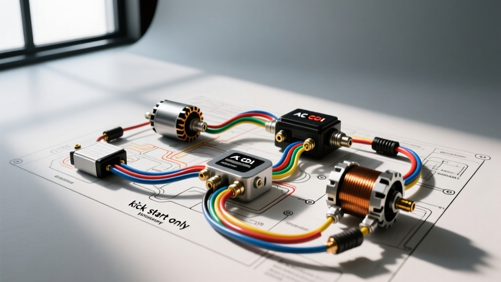
Architecture of a Batteryless Magneto System
Eliminating the battery from a pit bike reduces overall chassis weight, eliminates parasitic electrical draw, and removes a primary failure point in high-vibration, off-road environments. To successfully execute a without battery pit bike kick start only wiring diagram, the motorcycle must utilize an AC (Alternating Current) magneto system paired with an AC CDI (Capacitor Discharge Ignition) unit. Unlike DC-CDI systems found on larger street motorcycles, an AC-CDI draws its primary operating voltage directly from the stator's dedicated source coil the moment the kick-starter rotates the flywheel. This walkthrough details the exact wire routing, pin configurations, and gauge specifications required to wire 110cc, 125cc, and 140cc horizontal pit bike engines (such as YX, SSR, and Lifan clones) for strict kick-start operation.
Core Component Specifications & Wire Gauge Chart
Selecting the correct wire gauge is critical. Undersized wiring on the primary ignition circuit will cause voltage drop under high RPM, resulting in misfires. The following table outlines the standard Japanese/Chinese color codes and SAE J1128 compliant gauge requirements for batteryless pit bike harnesses.
| Component / Circuit | Standard Wire Color | Function | Recommended AWG |
|---|---|---|---|
| Stator Source Coil | Black / Red | High Voltage AC Power to CDI | 18 AWG (Stranded) |
| Pulse Generator (Trigger) | Blue / White | Timing Signal to CDI | 20 AWG (Shielded preferred) |
| Stator Lighting Coil | Yellow | AC Power for Headlight/Taillight | 16 AWG (Stranded) |
| System Ground | Green | Chassis / Engine Block Ground | 14 AWG (Stranded) |
| Kill Switch Circuit | Black / White | CDI Ground Interrupt (NC Switch) | 18 AWG (Stranded) |
| CDI to Ignition Coil | Black / Yellow | High Voltage Discharge to Coil | 16 AWG (High Dielectric) |
Step-by-Step Wiring Walkthrough
1. Stator Routing and Flywheel Air Gap
The stator sits behind the flywheel on the left side of the engine. Begin by inspecting the flywheel keyway. A sheared Woodruff key will alter the ignition timing, causing backfires through the carburetor even if the wiring is flawless. Route the stator harness through the engine case grommet, applying a liberal coat of dielectric grease to prevent moisture ingress and wire chafing. The pulse generator (pickup coil) must maintain an air gap of 0.015 to 0.025 inches from the flywheel trigger tab. If the gap is too wide, the low-amplitude signal will fail to trigger the CDI at low kick-start RPMs.
2. AC CDI Pinout and Integration
A standard 5-pin AC CDI is mandatory for a batteryless setup. Do not attempt to use a 4-pin or 6-pin DC CDI, as they require a 12V DC battery feed to operate the internal inverter. Wire the 5-pin connector as follows:
- Pin 1 (Blue/White): Connect to the stator pulse generator. This carries the low-voltage timing signal.
- Pin 2 (Green): Connect to the main chassis ground. Ensure this shares a clean, unpainted bolt on the frame.
- Pin 3 (Black/White): Connect to the handlebar kill switch. This is the grounding circuit.
- Pin 4 (Black/Red): Connect to the stator source coil. This supplies the raw 100V-400V AC needed to charge the CDI capacitor.
- Pin 5 (Black/Yellow): Connect to the primary terminal of the ignition coil.
3. Ignition Coil and HT Lead Routing
The ignition coil steps up the CDI's discharge voltage to roughly 15,000 - 30,000 volts. Mount the coil to the frame using rubber-isolated brackets to prevent high-frequency vibration from fracturing the internal windings. The primary side receives the Black/Yellow wire from the CDI. The secondary side utilizes a high-tension (HT) lead routed to the spark plug cap. Per SAE J1292 ignition standards, ensure the spark plug cap contains a 5k-ohm ceramic resistor to suppress RFI (Radio Frequency Interference), which can otherwise scramble the CDI's internal logic gate during high-RPM operation.
4. Kill Switch Logic (Normally Closed)
Because the system is AC magneto-based, the kill switch must be Normally Closed (NC). When the switch is in the 'RUN' position, the circuit is open, allowing the CDI to fire. When flipped to 'KILL', the switch bridges the Black/White wire to the Green ground wire, effectively shorting the CDI's internal thyristor gate and halting the spark. Wire the kill switch directly to the handlebar, utilizing marine-grade heat shrink over the solder joints to prevent sweat and mud from causing a dead short.
AC Lighting Coil Integration
Running a headlight without a battery requires tapping into the stator's dedicated lighting coil, typically identified by the Yellow wire. Unlike the ignition circuit, this output is raw, unregulated AC power that fluctuates wildly with engine RPM (roughly 6V at idle, spiking to 14V+ at high RPM).
If you are wiring a standard halogen bulb, connect the Yellow wire directly to the headlight switch, and ground the bulb housing to the frame. However, if you are installing modern LED lighting, you must install an inline AC-to-DC rectifier/regulator module between the Yellow stator wire and the LED headlight. LEDs operated directly on unregulated AC magneto power will flicker severely and suffer premature diode burnout due to reverse-voltage spikes. Reference MiniMotoTech Pit Bike Wiring Guides for specific inline regulator placement on YX and SSR stators.
Vibration-Proofing Off-Road Connections
Pit bikes generate severe high-frequency vibration, particularly from the solid-mounted horizontal engines. Standard vinyl electrical tape and butt connectors will fail within hours of riding. For every connection in this wiring diagram:
- Strip the wire using precision strippers to avoid nicking the copper strands.
- Apply flux and solder the joint using rosin-core solder.
- Slide adhesive-lined (dual-wall) marine heat shrink over the joint and apply heat until the inner sealant extrudes from both ends.
- Loom the entire harness in split-loom tubing and secure it to the frame using UV-resistant zip ties, leaving slack near the steering head to prevent wire tension during full-lock turns.
Troubleshooting Decision Tree: No-Spark Diagnostics
If the engine fails to fire after completing the wiring walkthrough, follow this diagnostic sequence before replacing components:
- Symptom: Zero Spark.
- Check 1: Is the kill switch grounded? Disconnect the Black/White wire at the CDI. If spark returns, the kill switch or handlebar wiring is shorted to ground.
- Check 2: Measure stator source coil resistance. Set multimeter to Ohms (Ω). Probe Black/Red to Green. A reading outside 100Ω - 400Ω indicates a burnt source coil.
- Check 3: Measure pulse generator resistance. Probe Blue/White to Green. Acceptable range is 90Ω - 150Ω. An open circuit means the pickup coil is dead.
- Symptom: Weak or Intermittent Spark.
- Check 1: Inspect the spark plug cap. Remove the cap from the HT lead, trim 1/4 inch off the wire to expose fresh copper, and re-thread the cap. Internal corrosion causes high resistance.
- Check 2: Verify the ignition coil ground. The metal bracket of the coil must have bare-metal contact with the frame. Paint or powder coating will interrupt the secondary circuit return path.
- Check 3: Check flywheel magnets. If the bike was pressure-washed or stored improperly, the flywheel magnets may have rusted or cracked, reducing the magnetic flux required to generate adequate voltage in the source coil.
Authoritative References
For further technical validation on automotive and motorcycle electrical standards, consult the following resources:
- SAE J1128: Low Tension Primary Cable Standard - Guidelines for wire gauge, insulation thickness, and thermal ratings in ignition circuits.
- SAE J1292: Ignition Coil Systems - Specifications for dielectric strength and RFI suppression in motorcycle ignition coils.
- MiniMotoTech Wiring Diagrams - Model-specific stator and CDI mapping for 110cc to 150cc pit bike platforms.