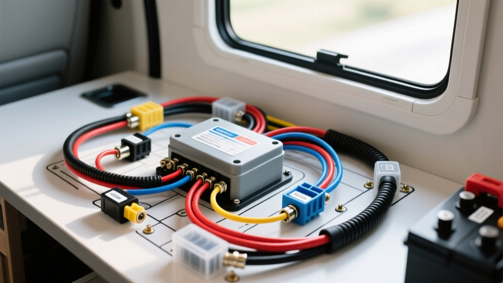
Mastering the Motorhome Battery Isolator Wiring Diagram
Upgrading or repairing the dual-battery system in a Class A or Class C motorhome requires a precise understanding of electrical separation and charging logic. At the heart of this system is the battery isolator, a critical component that allows the alternator to charge both the chassis (starting) and house (deep cycle) batteries while preventing the house loads from draining the starting battery. This complete motorhome battery isolator wiring diagram walkthrough will guide you through the exact circuit paths, wire gauges, fusing requirements, and real-world failure modes associated with continuous duty solenoids and solid-state isolators.
Core Components: Solenoid vs. Solid-State Isolator
Before tracing the wires, you must identify which type of isolator your RV utilizes. The wiring topology changes significantly between the two:
- Continuous Duty Solenoid (Bi-Directional Relay): Acts as a heavy-duty mechanical switch. When triggered by the ignition, an electromagnetic coil pulls contacts together, physically bridging the chassis and house battery banks. Common models include the Cole Hersee 24059 or Blue Sea Systems 9012.
- Solid-State Diode Isolator: Uses heavy-duty silicon diodes to route alternator output to both batteries simultaneously without allowing reverse current flow. These require no trigger wire but introduce a voltage drop (typically 0.6V to 1.0V) that must be compensated for at the alternator's sense wire.
Note: This walkthrough focuses on the continuous duty solenoid, as it is the industry standard for modern Class C and Class A motorhomes due to its zero voltage-drop characteristics across the main charging path.
Step-by-Step Circuit Walkthrough
A properly executed motorhome battery isolator wiring diagram consists of three distinct circuits: the chassis feed, the house feed, and the ignition trigger circuit. Below is the exact routing and specification for a standard 200A-250A solenoid setup.
Circuit 1: Chassis Battery to Isolator (Terminal A)
This circuit carries the raw charging current from the engine alternator and chassis battery to the isolator.
- Origin: Chassis battery positive post.
- Protection: Install a 250A Class T fuse within 7 inches of the battery terminal, as mandated by NFPA 1192 (Standard on Recreational Vehicles) to prevent catastrophic shorts.
- Conductor: Run 2/0 AWG tinned copper wire (Red jacket) from the fuse block to Terminal A on the solenoid.
- Termination: Use 3/8-inch adhesive-lined heat shrink ring terminals. Crimp with a hydraulic crimper and torque the solenoid nut to 120 in-lbs to prevent arcing.
Circuit 2: House Battery to Isolator (Terminal B)
This circuit routes the charging current from the solenoid to the house battery bank.
- Origin: House battery bank positive busbar.
- Protection: Install a second 250A Class T fuse within 7 inches of the house busbar. According to Blue Sea Systems circuit protection guidelines, both sides of the bridging solenoid must be fused because both battery banks are active power sources capable of delivering massive short-circuit current.
- Conductor: Run 2/0 AWG tinned copper wire (Red jacket) from the house fuse to Terminal B on the solenoid.
- Termination: Identical to Circuit 1. Ensure no stray wire strands are exposed near the solenoid chassis.
Circuit 3: Ignition Trigger & Ground (Terminals C & D)
The trigger circuit tells the solenoid when to engage. It must only activate when the engine is running to prevent the house lights from engaging the solenoid and draining the chassis battery.
- Coil Positive (Terminal C): Run 12 AWG wire (Yellow or Orange) from an ignition-switched "Run" circuit (often found at the fuse panel or ignition switch rear harness). Protect this line with a 10A inline ATC blade fuse.
- Coil Negative (Terminal D): Run 12 AWG wire (Black) from Terminal D to a clean, bare-metal chassis ground point. Use a star washer to bite through paint and ensure a resistance of less than 0.05 ohms to ground.
Technical Specifications & Wire Sizing Chart
Selecting the correct wire gauge is dictated by the maximum output of your RV's alternator and the length of the wire run. The following table aligns with SAE J1128 battery cable standards for high-amperage DC applications.
| Alternator Output | Main Cable AWG | Fuse Rating (Class T) | Terminal Lug Size | Max Run Length (One Way) |
|---|---|---|---|---|
| 100A - 140A | 1/0 AWG | 150A | 3/8" or 5/16" | 10 Feet |
| 150A - 200A | 2/0 AWG | 250A | 3/8" | 15 Feet |
| 220A - 300A | 4/0 AWG | 350A | 1/2" | 20 Feet |
| Trigger Circuit | 12 AWG | 10A (ATC) | #10 Ring | N/A (Low Current) |
The LiFePO4 Warning: Alternator Protection
If you are upgrading your house bank to Lithium Iron Phosphate (LiFePO4), a standard motorhome battery isolator wiring diagram is no longer safe. Lithium batteries accept charge at massive currents (often exceeding 200A continuously) and feature a Battery Management System (BMS) that will instantly disconnect the battery if it reaches full capacity or experiences a fault. If the BMS opens the circuit while the alternator is pushing 150A, the resulting voltage spike (load dump) will instantly destroy the alternator's diode bridge.
The Fix: Replace the standard solenoid with a DC-DC battery charger (e.g., Victron Orion-Tr Smart) or a BMS-compatible isolator relay (e.g., Victron Cyrix-Li) that communicates directly with the lithium BMS to throttle the alternator output before a disconnect occurs.
Real-World Troubleshooting Decision Tree
When the house batteries fail to charge while driving, use this diagnostic sequence to isolate the fault in the isolator circuit.
Symptom: Solenoid Clicks Rapidly but Batteries Don't Bridge
- Cause: Voltage drop in the 12 AWG trigger circuit. The coil is receiving enough voltage to pull the contacts, but the voltage drops under the coil's amperage draw, causing it to release and chatter.
- Fix: Perform a voltage drop test across the trigger wire. If the drop exceeds 0.5V under load, replace the 12 AWG wire with 10 AWG or clean the ignition-run splice connection.
Symptom: Solenoid Engages, but House Battery Voltage Remains Below 13.2V
- Cause: High resistance across the main solenoid contacts (Terminal A to Terminal B) due to internal carbon tracking or pitting from repeated engagement under load.
- Fix: With the engine running and solenoid engaged, measure the DC voltage directly on the metal stud of Terminal A, then Terminal B. If the difference is greater than 0.15V, the internal contacts are burned. Replace the continuous duty solenoid.
Symptom: Chassis Battery Drains Overnight When Parked
- Cause: The solenoid contacts have physically welded together due to high-current arcing, keeping the chassis and house banks permanently bridged. Alternatively, the trigger wire is tied to a constant 12V source instead of an ignition-switched source.
- Fix: Disconnect the 10A inline trigger fuse. If the solenoid remains engaged and the batteries still read identical voltages, the solenoid is welded shut and must be replaced. Verify the trigger wire source with a multimeter; it must read 0V when the ignition key is removed.
Final Installation Best Practices
Always mount the battery isolator solenoid in a dry, ventilated compartment away from battery off-gassing (hydrogen sulfide). Use nylon lock nuts on the solenoid studs to prevent vibration from loosening the heavy 2/0 AWG cables over thousands of miles of highway driving. Finally, coat all exposed copper and terminal connections with dielectric grease or a marine-grade corrosion inhibitor to prevent galvanic corrosion in humid camping environments.