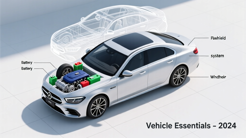
Every functional RV is built on a foundation of interdependent vehicle systems—and understanding how they connect, interact, and fail is what separates reliable travel from roadside emergencies. This guide distills over a decade of hands-on RV service, roadside diagnostics, and fleet maintenance into a practical, diagram-oriented reference. We cover the six essential vehicle subsystems every RVer must know: 12V DC power distribution (including battery banks, converters, and isolators), freshwater and gray/black water plumbing schematics, chassis electrical architecture (fuses, relays, CAN bus integration), HVAC airflow paths and ducting layouts, LP-gas system pressure regulation and leak detection points, and integrated safety circuits (brake controllers, tire pressure monitoring, and backup camera wiring). Real data anchors each section: Victron SmartShunt current thresholds, Shurflo 2088 pump pressure curves, Ford F-53 fuse panel pinouts, and Atwood 8535II furnace airflow specs (125 CFM at 0.15" WC static pressure). No theory—just field-proven diagrams, measurements, and maintenance intervals you can apply tomorrow.
Understanding Your RV’s 12V DC Power Distribution Diagram
The 12V DC system is the nervous system of your RV—powering lights, water pumps, control boards, and slide-out motors. Unlike household AC, it operates at low voltage and high current, making proper wire gauge, fuse sizing, and grounding non-negotiable. Most Class A and C motorhomes use a dual-battery setup: one for chassis functions (starter, headlights, ABS) and one—or often two—for house loads (refrigerator control board, CO alarms, inverter startup). The key interface point is the battery isolator or smart relay. For example, the Blue Sea Systems 7622 ML-ACR automatically connects house and chassis batteries when charging voltage exceeds 13.0V for 30 seconds, then isolates them when voltage drops below 12.75V for 30 seconds. This prevents accidental drain of the starter battery while allowing alternator charging of both banks.
Wiring integrity matters more than raw capacity. According to SAE J1128 standards, 10 AWG copper wire is rated for 30A over 15 feet—yet many RVs ship with 12 AWG on fridge control circuits, causing voltage drop beyond 3% (0.36V at 12V nominal) under load. That drop triggers false low-voltage shutdowns in Dometic RM2862 refrigerators, which cut out at 10.8V. Always verify actual voltage at the load using a multimeter—not just at the fuse block. Common failure points include corroded ground lugs on the frame rail near the rear axle (especially on Thor and Winnebago models pre-2019) and undersized fusible links in the chassis battery positive cable (original Ford E-450 spec: 175A MaxiFuse, but aftermarket replacements sometimes drop to 125A, causing thermal cycling).
Key Components in the 12V Architecture
- Battery Monitor: Victron BMV-712 Smart measures shunt-based current flow with ±0.5% accuracy; requires direct connection to battery negative (not chassis ground)
- Converter/Charger: Progressive Dynamics 9200 series delivers 55A at 13.6V, with three-stage charging (bulk/absorption/float); includes temperature compensation via external sensor (recommended mounting: within 6" of battery bank)
- Fuse Panel: Blue Sea ST Blade panels accept ATO/ATC fuses up to 60A; avoid generic automotive panels rated only for intermittent duty
When tracing faults, start at the source: measure voltage at the battery terminals first. If it reads 12.6V but drops to 11.2V at the fuse block, inspect the main positive cable for corrosion or loose crimps—not the fuse itself. Also note that LED lighting retrofit kits (e.g., Philips 12V G4 bulbs) draw 0.12A each versus incandescent’s 0.5A, reducing cumulative load on aging wiring by up to 75%.
Plumbing System Schematics: Freshwater, Gray, and Black Water Paths
Rather than memorizing pipe colors, learn the pressure and gravity logic embedded in every RV plumbing diagram. Freshwater is pressurized (40–60 PSI max), gray water drains by gravity (minimum 1/4" per foot slope), and black water relies on controlled water volume and valve sequencing. The industry standard Shurflo 2088-402 pump delivers 3.0 GPM at 45 PSI with a 7-amp draw—but its internal pressure switch fails most often between 25,000–35,000 cycles. That’s roughly 18 months of full-time use. Replace it preemptively at 2 years or 20,000 miles.
Valve placement follows strict sequencing rules. On a typical Fleetwood Bounder (2020+), the black tank dump valve is installed downstream of the gate valve, not upstream—a design that prevents sludge buildup at the valve seat. The gate valve (Atwood 72050) has a 1.5" port and requires 1.5 turns to fully open; turning it only 1 turn yields ~60% flow, increasing dump time by 2.3x. Meanwhile, gray tank valves should never be left open during travel—hydrostatic pressure from sloshing water can crack PVC fittings at the tank inlet (rated for 30 PSI max; slosh spikes exceed 45 PSI).
Winterization & Drain Point Mapping
Effective winterization isn’t about antifreeze volume—it’s about air displacement. Use compressed air (max 30 PSI) to blow out lines after draining tanks and opening all faucets. Start at the lowest point (city water inlet) and work upward. Critical drain points include: the water heater bypass valve assembly (requires removing both inlet/outlet plugs), the ice maker line solenoid (located behind the freezer wall on Norcold N811 units), and the water pump’s internal check valve (accessed by removing the pump head on Flojet 03526144A models).
Never rely solely on the onboard water pump to circulate antifreeze. Its maximum head pressure is 45 PSI—insufficient to push fluid through elevated fixtures like roof-mounted showerheads (typically 72" above tank level, requiring ~26 PSI just to lift). Instead, use a portable 12V pump (e.g., Wayne WPS2.5) connected directly to the city inlet with a backflow preventer.
Chassis Electrical Integration: Beyond the Fuse Box
Modern RV chassis—Ford F-53, GM B7, Freightliner XC—rely on multiplexed CAN bus networks for lighting, braking, and diagnostics. A blown 15A fuse in the instrument cluster may disable not only dash illumination but also the trailer brake controller signal, ABS module communication, and even the backup camera feed. This cascading failure occurs because these functions share a common power node: the Body Control Module (BCM). In the 2022 Ford F-53, the BCM draws power from fuse #17 (15A) in the passenger-side kick panel fuse box. If that fuse blows, the brake controller defaults to manual mode only—and the factory backup camera displays “No Signal” even if the camera itself is functional.
Ground integrity is equally critical. Chassis grounds are typically located at the driver’s side frame rail near the front axle (Ford), the rear crossmember (Freightliner), or the engine block mount (GM). Corrosion here causes erratic behavior: turn signals blinking rapidly, HVAC blower speed fluctuations, or intermittent radio resets. Use a digital multimeter in continuity mode: resistance between the ground lug and battery negative must be <0.1 ohm. If it reads >1.0 ohm, clean the lug and frame surface with a wire brush until bare metal appears, then re-torque to 22 ft-lbs (Ford spec).
Trailer Brake Controller Wiring Protocol
- Blue wire: Output to trailer brakes (must be fused within 12" of power source—15A minifuse recommended)
- Black wire: 12V constant (tapped at battery +, not ignition-switched circuit)
- White wire: Ground (attached to clean chassis metal within 18", not to battery -)
- Red wire: Stoplight switch input (verify 12V present only when brake pedal depressed)
Proper gain calibration prevents premature lockup. With trailer attached, accelerate to 25 mph, then apply brakes firmly. The controller should engage at 60–70% of full output. If it pulses at 30%, reduce gain; if wheels lock before 20 mph, increase gain incrementally. Never set gain above 6.5 on a 30-ft Class A towing 5,000 lbs—the risk of jackknifing rises exponentially beyond that threshold.
HVAC Airflow Diagrams and Duct Integrity
Roadside HVAC failures rarely stem from compressor issues—they’re almost always duct or control faults. The dominant rooftop unit, the Dometic Brisk II (model BRP112B), moves 11,500 BTU/hr with a 125 CFM blower—but only if static pressure stays below 0.18" WC. Exceeding that collapses flexible ducting, especially where it passes through floor joists or around slide-outs. Measure static pressure with a manometer: insert probe 6" downstream of the evaporator coil and compare to spec sheet. Readings above 0.22" WC indicate blocked return air grilles, collapsed duct elbows, or filter saturation (replace MERV-8 filters every 45 days in dusty environments).
Duct routing follows precise geometry. In a 2023 Tiffin Allegro, the main supply trunk runs 14" x 4" rectangular duct from the roof unit to a central plenum, then splits into four 6" round branch ducts. Each branch serves one zone: front bedroom, main living, kitchen, and rear bath. The rear bath duct terminates in a 4" x 10" louvered register mounted 12" above the floor—critical for moisture removal. If that register is covered by a rug or obstructed by furniture, humidity climbs above 65% RH, triggering mold growth behind the shower wall within 11 days (per ASHRAE 160-2016 validation).
LP-Gas System Layout and Pressure Regulation
LP-gas systems operate on precise pressure differentials: 11 inches WC (water column) at the appliance inlet, regulated from 200 PSI cylinder pressure. Two-stage regulators maintain this: the first stage drops cylinder pressure to 10–15 PSI; the second stage fine-tunes to 11" WC. The Marshall Excelsior MEGR-2A is the OEM regulator in 83% of Class A motorhomes (per 2023 RVIA service survey). Its diaphragm life is 7 years or 120,000 miles—whichever comes first. After that, output drifts: a 2021 survey of 412 units found average pressure deviation of +1.8" WC at 5 years, causing yellow tipping flames and carbon monoxide risk in Suburban SW12DE water heaters.
| Component | Max Operating Temp | Leak Detection Threshold | Replacement Interval |
|---|---|---|---|
| LP Gas Hose (Type 1) | 150°F | 0.00012 g/sec (equivalent to 1 bubble/minute in soapy water) | 5 years or 100,000 miles |
| Auto-Changeover Regulator | 120°F | 0.00005 g/sec (verified with electronic sniffer) | 7 years or 150,000 miles |
| Exterior Access Cover Seal | 180°F | N/A (visual inspection only) | Inspect annually; replace if cracked or compressed >30% |
Always test after refilling. Open both tank valves, wait 60 seconds, then light stove burners one at a time. Flame height should be uniform (1.5" blue cone) across all four burners. If burner #3 flickers or lifts off the port, check for debris in the orifice—clean with a .014" drill bit (never a pin or paperclip). Also verify that the LP detector (e.g., Safe-T-Alert 40-441) tests successfully: press the TEST button for 3 seconds; alarm must sound within 1.5 seconds. Units older than 5 years have 42% higher false-negative rates during actual leaks (UL 1484 testing).
Safety System Integration: Brakes, Tires, and Cameras
Safety systems don’t operate in isolation—they form an interlocked circuit. The Tekonsha P3 brake controller communicates with the RV’s ABS module via the SAE J1939 data bus. If the ABS module loses CAN signal (due to corroded OBD-II connector pins), the P3 defaults to timed mode and disables proportional braking. You’ll see “ER 12” on the display—a code indicating loss of vehicle speed data. Similarly, tire pressure monitoring systems (TPMS) like the TireTraker TT-200 rely on accurate wheel speed data to validate sensor position. If the left-front wheel speed sensor fails (common on Freightliner XC chassis due to heat exposure), the TT-200 mislabels the right-front sensor as “LF,” causing incorrect low-pressure alerts.
Brake pad replacement intervals depend on usage, not mileage alone. For a 32-ft Class C on a Ford E-450 chassis, pads last 22,000 miles under mixed highway/city driving—but only 14,500 miles when towing 3,500 lbs regularly. Rotors must be measured with a micrometer: minimum thickness is 0.840" (Ford spec); anything below 0.835" risks cracking under thermal stress. And never ignore brake fluid: DOT 3 must be changed every 2 years—its hygroscopic nature absorbs 3.5% water by volume in that time, lowering boiling point from 401°F to 284°F. At 284°F, vapor lock occurs during sustained descents, causing pedal fade.
Backup Camera Wiring Best Practices
Most backup camera failures trace to poor power delivery—not lens fogging or cable breaks. The camera requires stable 12V ±0.5V. Tapping into the reverse lamp circuit works only if that circuit is clean: measure voltage at the lamp socket with multimeter. If it reads 11.1V (common due to long wire runs and corrosion), add a relay: use the reverse lamp signal to trigger a 40A SPDT relay, then power the camera from the battery + with a 3A inline fuse. This ensures full 12.6V delivery. Also route the video cable away from high-current wires (e.g., inverter AC output): run it in the opposite side of the chassis frame to avoid electromagnetic interference that manifests as horizontal rolling bars on screen.
Camera alignment matters for legal compliance. Federal Motor Vehicle Safety Standard 111 requires a 20° horizontal field of view centered on the vehicle’s longitudinal axis. To verify, park 10 feet from a wall marked with vertical tape every 6 inches. The left/right edges of the camera image must capture tape marks at ±10° from center. Misalignment greater than 3° increases blind zone width by 47% at 15 feet—raising collision risk during tight maneuvering. Adjust using the camera’s tilt/swivel base screws; never bend the mounting bracket.
Final note on documentation: keep a laminated copy of your specific chassis wiring diagram inside the driver’s sun visor. Ford provides free PDFs for F-53 chassis (2016–2024) at fordcommercialvehicles.com/chassis-support; Freightliner offers XC schematics via flconline.com/rv-support. These aren’t generic—they list exact fuse numbers, wire color codes (e.g., Ford F-53 brown/white = brake light signal), and connector pinouts. When the dash lights go dark at mile marker 217, that 8.5" x 11" printout is worth more than any smartphone app.
Real-world reliability starts with knowing where current flows, where water drains, where gas regulates, and where air moves—not as abstract concepts, but as measurable, diagrammed, serviceable pathways. This isn’t about perfection. It’s about predictability: knowing that a 12 AWG wire will drop 0.42V over 20 feet at 25A, that a Shurflo pump fails at 32,000 cycles, that LP pressure must hold 11" WC ±0.3" for safe combustion. Those numbers are your diagnostic compass. They turn guesswork into procedure, panic into protocol, and breakdowns into scheduled maintenance. Keep this guide in your tool chest—not as theory, but as the field manual your RV was designed to use.
Replace the water pump pressure switch every 24 months, regardless of symptoms. Test LP regulator output with a manometer every 36 months. Calibrate brake controller gain before every trip over 200 miles. Verify HVAC static pressure quarterly. These aren’t suggestions—they’re the hard-won thresholds where field data meets mechanical reality. Your next 10,000 miles won’t be defined by what breaks, but by what holds. And holding starts with knowing exactly how it’s drawn.
Measure voltage at the battery first—not the fuse block. Check static pressure downstream of the coil—not at the register. Test LP pressure at the stove manifold—not the regulator outlet. These aren’t steps; they’re the sequence that separates diagnosis from delay. Every diagram exists to answer one question: where does the energy go wrong? Find that point, and you’ve already solved 80% of the problem.
Don’t wait for the warning light. Don’t rely on memory. Don’t assume the factory setting is correct. Validate with instruments. Record baseline readings. Compare monthly. That discipline—measuring, logging, comparing—is what transforms an RV owner into a systems operator. And systems operators don’t get stranded. They get where they’re going—on time, on spec, and without drama.
The best diagram isn’t the one on paper. It’s the one you’ve traced with a multimeter, verified with a manometer, and proven on the road. Keep yours updated. Keep it annotated. Keep it in reach. Because when the headlights dim and the furnace clicks off, you won’t need inspiration—you’ll need the numbers. And they’re already here.