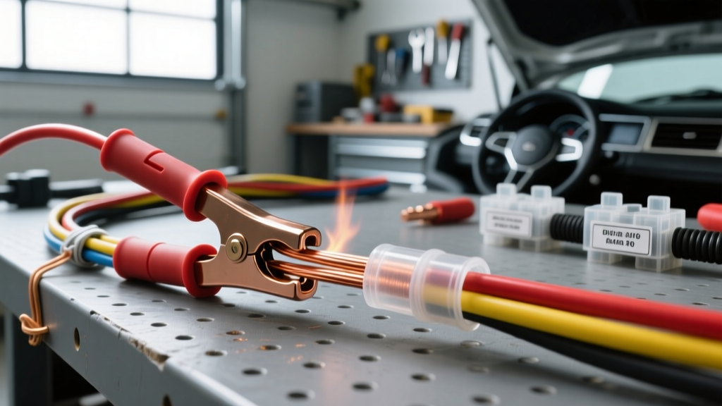
The Critical Role of Ground Wire Splices in Automotive Circuits
In automotive electrical systems, the ground wire is not merely a safety feature; it is the primary return path to the battery negative terminal. When a ground wire becomes corroded near a chassis mounting point or is damaged within a harness, splicing in a new section of wire is often necessary to restore circuit integrity. However, splicing a ground circuit introduces a potential failure point. If executed poorly, a ground wire splice connector can introduce resistance, leading to voltage drops, erratic ECU behavior, dim lighting, or fuel pump starvation.
This practical installation guide details the exact procedures for installing a marine-grade, adhesive-lined ground wire splice connector. We will focus on 10 AWG to 18 AWG automotive primary wires (such as TXL or GXL), ensuring a watertight, low-resistance repair that meets or exceeds OEM standards. Whether you are repairing a 10 AWG black fuel pump ground on a late-model Ford F-150 or extending an 18 AWG sensor ground before it enters a Molex MX150 connector cavity, the principles of proper crimping and thermal sealing remain identical.
Selecting the Correct Ground Wire Splice Connector
The most common mistake in DIY automotive wiring is using standard vinyl or nylon insulated butt splices for ground repairs. These materials are susceptible to capillary action, which wicks moisture directly into the copper strands. Over time, this causes galvanic corrosion, resulting in green copper oxide (verdigris) that drastically increases electrical resistance.
For any ground wire splice connector installation, you must use adhesive-lined polyolefin heat shrink butt connectors. The outer shell is made of dual-wall polyolefin that shrinks at a 3:1 ratio, while the inner lining features a thermoplastic adhesive. When heated, this adhesive melts and flows into the wire strands, creating a 100% waterproof and airtight seal. According to the Waytek Marine-Grade Heat Shrink Terminals Guide, this adhesive barrier is critical for preventing the oxidation that plagues ground circuits exposed to road salt and undercarriage moisture.
Tools and Materials Required
- Wire: SAE J1128 compliant TXL (Thin-wall) or GXL (General) automotive primary wire. Match the AWG and color (typically Black for GM/Chrysler grounds, or Brown/White tracer for Ford).
- Connectors: Adhesive-lined heat shrink butt splices (Red for 22-16 AWG, Blue for 16-14 AWG, Yellow for 12-10 AWG).
- Crimper: Ratcheting terminal crimper with dedicated insulated terminal dies (e.g., Titan or Glarks ratchet crimpers).
- Strippers: Precision wire strippers calibrated for TXL thin-wall insulation.
- Heat Source: Variable temperature heat gun (capable of 350°F / 175°C). Avoid open-flame torches.
- Testing: Digital Multimeter (DMM) for voltage drop testing.
Step-by-Step Installation Guide
Step 1: Isolate and Prepare the Circuit
Disconnect the negative battery terminal using a 10mm or 8mm socket to prevent short circuits. Locate the damaged section of the ground wire. Cut out the corroded or frayed section. If the damage extends close to a connector (such as a Deutsch DT or Molex MX150), ensure you leave at least 1.5 inches of clean wire to work with before the terminal pin cavity.
Step 2: Precision Wire Stripping
Strip the insulation from both the harness ground wire and your new TXL replacement wire. The strip length must precisely match the depth of the metal barrel inside the butt connector, plus 1/16th of an inch. Stripping too little wire results in the crimp die biting into the copper strands, weakening them. Stripping too much leaves exposed copper outside the heat shrink, inviting corrosion.
Step 3: The Ratchet Crimp
Insert the first wire into the metal barrel of the ground wire splice connector. Place the connector into the ratcheting crimper. For insulated heat shrink terminals, the crimp die features two distinct cavities. The deeper, more rounded cavity must crimp the metal barrel over the bare copper, while the shallower, wider cavity crimps the insulation sleeve over the wire jacket. Squeeze the ratchet until it releases. The TE Connectivity Application Spec 114-10001 emphasizes that a proper crimp should exhibit a slight bellmouth at the wire entry point to prevent the sharp barrel edge from shearing strands under vibration. Repeat for the second wire.
Step 4: Thermal Activation and Sealing
Set your heat gun to approximately 350°F (175°C). Apply heat to the center of the connector first, then slowly sweep outward toward the wire entries. As the polyolefin shrinks, you will see a small bead of clear thermoplastic adhesive squeeze out of both ends. This bead is the visual confirmation of a watertight seal. Do not overheat, as burning the polyolefin will compromise its dielectric strength.
Ground Wire Splice Connector Specification Chart
Refer to the table below to ensure you are matching the correct connector color, strip length, and wire type to your specific automotive ground repair. These specifications align with the SAE J1128 Standard for Low Tension Primary Cable.
| Wire Gauge (AWG) | Connector Color | Strip Length (Inches) | Typical Automotive Application | Crimp Die Selection |
|---|---|---|---|---|
| 22 - 18 AWG | Red | 0.25" - 0.30" | ECU Sensor Grounds, CAN-Bus Shields | Red / 1.5mm² |
| 16 - 14 AWG | Blue | 0.30" - 0.35" | Lighting Circuits, Relay Coil Grounds | Blue / 2.5mm² |
| 12 - 10 AWG | Yellow | 0.38" - 0.45" | Fuel Pumps, ABS Modules, Amplifiers | Yellow / 6.0mm² |
Validating the Repair: Voltage Drop Testing
Because ground circuits carry the full return current of the component, even a fraction of an ohm of resistance at your new ground wire splice connector can cause severe issues. You must validate the repair using a voltage drop test under load.
- Reconnect the battery negative terminal.
- Set your Digital Multimeter to DC Volts.
- Place the Red probe directly on the battery negative post (not the clamp).
- Place the Black probe on the component side of your new ground splice.
- Activate the circuit (e.g., turn on the fuel pump or headlights).
Acceptable Thresholds: For low-current sensor grounds (18 AWG), the voltage drop should be less than 0.05V. For high-current accessory grounds (10 AWG), the maximum acceptable voltage drop across the splice and the remaining wire to the chassis is 0.10V to 0.20V. If your reading exceeds 0.20V, your crimp is insufficient, or the wire strands were compromised during stripping.
Common Ground Splicing Mistakes to Avoid
1. Using Piercing Connectors (T-Taps): Never use Scotch-Loks or saddle connectors to tap into an existing ground wire. These connectors rely on a small metal blade that pierces the insulation, severing copper strands and introducing a high-resistance point that will inevitably corrode.
2. Soldering Instead of Crimping: While soldering is common in household electronics, the SAE and most automotive OEMs strongly advise against soldering under-hood wire splices. Solder creates a rigid joint that work-hardens and fractures under the constant vibration of a vehicle chassis. A properly executed ratchet crimp creates a cold-weld that remains flexible and gas-tight.
3. Ignoring Galvanic Compatibility: Always ensure your replacement wire and the harness wire are both copper. Never splice a copper ground wire into an aluminum chassis ground strap without a specialized bi-metallic lug, as the dissimilar metals will rapidly corrode when exposed to electrolytes (road water and salt).
By strictly adhering to adhesive heat-shrink protocols and utilizing precision ratchet crimpers, your ground wire splice connector installation will provide a permanent, OEM-grade repair capable of surviving the harsh thermal and vibrational environments of modern automotive undercarriages and engine bays.