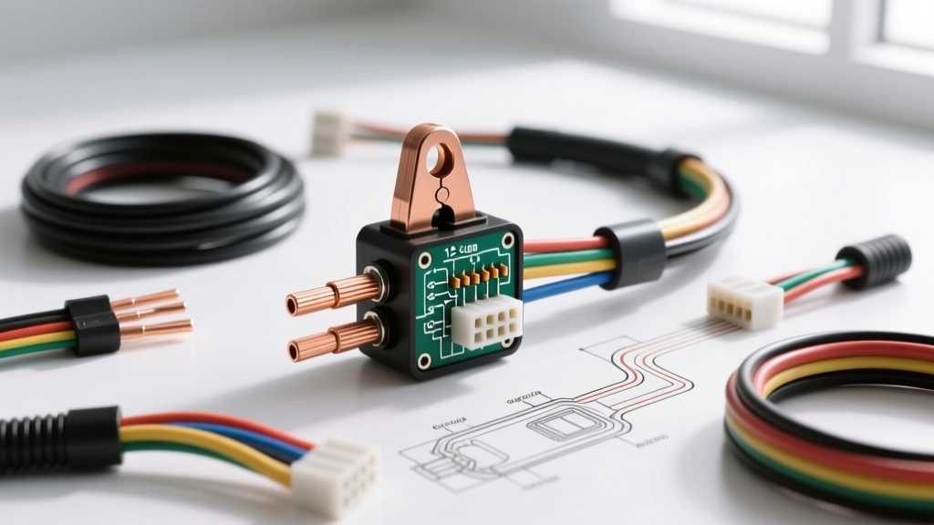
Introduction: Translating Diagrams to Physical 12 AWG Harnesses
Reading an automotive wiring diagram is only the first step in executing a flawless electrical repair or custom harness build. The true test of an automotive electrician lies in translating those schematic lines into physical reality, especially when dealing with high-current circuits. In modern and classic vehicles alike, 12 AWG (American Wire Gauge) wire is the undisputed workhorse for circuits drawing between 20 and 40 amps. This includes fuel pumps, engine cooling fans, high-beam headlights, and main power distribution blocks.
When cataloging wire connectors 12 gauge terminals and splices fall into a critical medium-high current bracket. A poor connection here does not just cause a voltage drop; it generates enough resistive heat to melt connector housings, degrade insulation, and potentially start an engine bay fire. This complete wiring diagram walkthrough will guide you through interpreting a standard high-current relay circuit, selecting the exact 12 AWG connectors required, and executing aerospace-grade crimps that meet OEM specifications.
Diagram Breakdown: The Standard ISO Mini-Relay Circuit
To understand how 12 gauge wire integrates into a vehicle's electrical system, we must walk through a standard 4-pin ISO mini-relay diagram (often referred to as a Bosch-style relay). This relay acts as a heavy-duty remote switch, allowing a low-current trigger circuit to control a high-current 12 AWG load circuit. According to standard AutoShop 101 Wiring Diagram Guides, the pins are numbered according to DIN 72552 standards.
The High-Current Path: Pins 30 and 87
- Pin 30 (Common / Power In): This pin receives direct battery voltage. In a fuel pump or cooling fan diagram, Pin 30 is fed by a 12 AWG Red wire originating from the main fusible link or power distribution center. It must handle the full inrush and continuous current of the load.
- Pin 87 (Normally Open / Power Out): When the relay coil is energized, the internal contactor bridges Pin 30 to Pin 87. The diagram will show a 12 AWG Blue wire exiting Pin 87, traveling through the firewall or along the frame rail, and terminating at the positive terminal of the accessory motor.
The Low-Current Control Path: Pins 85 and 86
- Pin 86 (Coil Power): Fed by a switched 12V source (e.g., ignition run/start or an ECU trigger). The diagram specifies an 18 AWG Pink/White wire. Because the relay coil only draws 150mA to 300mA, 12 gauge wire is unnecessary and physically incompatible with the smaller control circuit pins.
- Pin 85 (Coil Ground): Routes to the ECU (for PWM or ground-side switching) or a clean chassis ground using an 18 AWG Black wire.
Selecting the Correct 12 Gauge Wire Connectors
The physical execution of Pins 30 and 87 requires terminals capable of handling high amperage without exceeding a 0.1V drop across the connection point. Standard stamped-steel open-barrel terminals or cheap vinyl-insulated butt splices will fail under sustained 30A loads due to high contact resistance and vibration-induced fretting corrosion.
For professional harness building and diagram-accurate repairs, you must match the connector series to the environment and current draw. The Aptiv Metri-Pack 280 Series is the industry standard for 12 AWG high-current engine bay applications, utilizing a 2.8mm blade width rated for up to 30 amps. For slightly lower draws or sealed exterior connections, the Weather-Pack series is preferred.
12 AWG Connector Specification Chart
| Connector Type | Terminal Series | Max Continuous Current | Wire Range (AWG) | Crimp Die Color |
|---|---|---|---|---|
| Metri-Pack (Sealed) | 280 Series Female/Male | 30 Amps | 12 - 10 AWG | Yellow (12-10) |
| Weather-Pack (Sealed) | Tower / Shroud | 20 Amps | 12 - 10 AWG | Yellow (12-10) |
| Heat Shrink Butt Splice | Polyolefin Dual-Wall | 40 Amps (Splice) | 12 - 10 AWG | Yellow (12-10) |
| Ring Terminal (Stud) | Non-Insulated Copper | 50+ Amps | 12 - 10 AWG | Yellow (12-10) |
Wire Preparation: TXL vs. GPT Insulation
Before crimping any connector, the wire itself must meet SAE J1128 standards for low-tension primary cable. Never use standard hardware store THHN or generic PVC wire in an engine bay. Standard PVC (GPT) is rated for only 90°C and becomes brittle when exposed to exhaust radiant heat.
Always use TXL (Thin-wall Cross-Linked) or GXL wire for 12 gauge engine bay circuits. TXL insulation is rated to 125°C, resists abrasion, and its thin wall profile allows for easier routing through tight firewall grommets. When stripping 12 AWG TXL wire for a Metri-Pack 280 terminal, the strip length must be exactly 7.0mm to 7.5mm. Stripping too short leaves exposed copper behind the insulation crimp, leading to corrosion wicking. Stripping too long exposes bare copper between the terminal and the connector housing, creating a short-circuit hazard.
Executing the OEM-Grade Crimp
A proper crimp is a cold-weld process. The terminal barrel must be deformed around the copper strands in a way that creates a gas-tight seal, preventing oxygen from entering and causing galvanic corrosion. For 12 AWG wire, you must use a ratcheting crimp tool with a Yellow die (12-10 AWG).
Step-by-Step Crimping Procedure
- Strip the Wire: Use a precision wire stripper. Do not use razor blades or pliers, as nicking the outer copper strands reduces the effective cross-sectional area of the 12 AWG wire (3.31 mm²) and creates a localized hot-spot.
- Position the Terminal: Place the Metri-Pack 280 terminal in the yellow die of the crimp tool. Ensure the seam of the stamped terminal barrel is facing up or centered, never resting against the bottom anvil, which can cause the seam to split during compression.
- The Conductor Crimp: Insert the stripped 12 AWG strands until they bottom out in the terminal. Squeeze the tool. The conductor wings should fold inward in a 'B' or 'W' shape, biting into the copper strands.
- The Insulation Crimp: Move to the secondary die (usually marked for the outer grip). The insulation wings must wrap tightly around the TXL jacket without piercing it. This provides strain relief, ensuring that any pulling force on the wire is absorbed by the jacket, not the delicate copper crimp.
- Verify the Bellmouth: Inspect the front of the conductor crimp. You must see a tiny protrusion of copper strands (approx 0.5mm to 1.0mm) known as the "bellmouth" or "wire brush." This proves the wire was fully seated before the crimp was applied.
Troubleshooting Voltage Drop in 12 Gauge Circuits
Even if a wiring diagram is followed perfectly and the correct wire connectors are used, real-world variables can introduce resistance. If a fuel pump is starving for voltage or a cooling fan is running slow, do not immediately replace the component. Perform a voltage drop test across the 12 gauge circuit.
Set your multimeter to DC Volts. Place the red probe on the battery positive terminal and the black probe on the load side of the relay (Pin 87 output). With the circuit energized and drawing current, the meter should read less than 0.2V. If you read 0.8V or higher, you have a high-resistance fault. Common failure modes in 12 gauge circuits include:
- Cold Crimps: Using the wrong die size (e.g., using the Red 22-18 AWG die on a 12 AWG terminal) results in a loose mechanical connection. Under a 25A load, this will generate massive heat.
- Strand Cutting: Improper stripping that cuts 3 or 4 strands of the 19-strand 12 AWG bundle effectively downgrades the wire to 14 AWG, increasing resistance.
- Corroded Weather-Pack Seals: If the silicone ribbed seals are not pushed fully onto the 12 AWG wire before crimping, moisture bypasses the seal and corrodes the terminal from the inside out.
Conclusion
Mastering automotive wiring diagrams requires more than just tracing lines on a page; it demands a deep understanding of the physical materials that carry the electrons. By selecting the correct TXL wire, utilizing sealed Metri-Pack or Weather-Pack connectors, and executing gas-tight crimps with the proper yellow 12-10 AWG dies, you ensure that your high-current circuits will survive the harsh vibration and thermal cycles of the automotive environment. Always verify your work with a voltage drop test to guarantee OEM-level reliability.