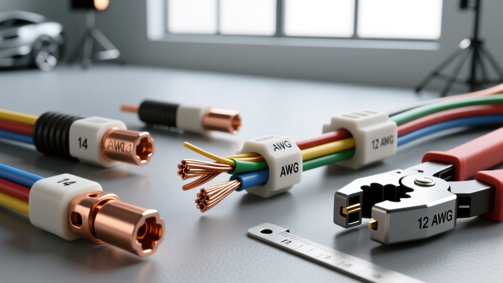
Introduction to Automotive Wire Splice Standards
In automotive electrical systems, the integrity of a wiring harness relies heavily on the quality of its terminations and splices. Wire splices are critical junction points used to join two or more conductors end-to-end, repair damaged harness sections, or integrate aftermarket accessories into OEM circuits. Unlike household electrical work, automotive environments subject wire splices to extreme thermal cycling, high-frequency vibration, and corrosive chemical exposure. Consequently, industry-standard splicing procedures are governed by rigorous specifications, most notably the SAE/USCAR-21 standard for crimped connections and the IPC/WHMA-A-620 standard for wire harness assemblies. Understanding the technical specifications of wire splices—including American Wire Gauge (AWG) mappings, barrel dimensions, environmental sealing metrics, and destructive testing thresholds—is mandatory for any automotive electrical engineer or master technician.
Anatomy and Dimensional Specifications of Butt Splices
The most common configuration in field repair and harness manufacturing is the closed-barrel butt splice. A properly engineered butt splice features two distinct crimp zones: the conductor crimp and the insulation crimp. The conductor crimp must deform the metal barrel around the copper strands to create a cold-weld gas-tight seal, while the insulation crimp provides strain relief by gripping the wire jacket. According to IPC/WHMA-A-620 acceptance criteria, a perfect conductor crimp must exhibit a visible 'bellmouth' at the rear of the barrel to prevent the sharp edge of the splice from shearing the copper strands during vibration.
Automotive wire splices are universally color-coded to correspond with specific AWG ranges and their metric equivalents. This color coding ensures that the internal barrel diameter matches the wire cross-section, preventing under-crimping (which leads to high resistance and thermal runaway) or over-crimping (which severs strands and weakens tensile strength).
| Color Code | AWG Range | Metric (mm²) | Strip Length (in/mm) | Barrel ID (in) | Min Pull-Out Force (lbs) |
|---|---|---|---|---|---|
| Red | 22 - 18 AWG | 0.35 - 0.80 mm² | 0.25 in / 6.4 mm | 0.045 | 20 lbs (89 N) |
| Blue | 16 - 14 AWG | 1.00 - 2.00 mm² | 0.31 in / 7.9 mm | 0.070 | 30 lbs (133 N) |
| Yellow | 12 - 10 AWG | 2.50 - 6.00 mm² | 0.38 in / 9.6 mm | 0.105 | 50 lbs (222 N) |
Environmental Sealing: Heat Shrink and Adhesive Liners
For wire splices located in the engine bay, chassis, or wheel wells, unsealed nylon or vinyl insulated splices are strictly prohibited due to the risk of galvanic corrosion and moisture ingress. Sealed environments require dual-wall, adhesive-lined heat shrink wire splices. These splices utilize an outer jacket made of cross-linked polyolefin and an inner liner composed of ethylene-vinyl acetate (EVA) thermoplastic adhesive.
When heated to approximately 120°C (248°F), the polyolefin outer wall shrinks at a 3:1 or 4:1 ratio, while the EVA inner liner melts and flows into the interstitial spaces between the copper strands and the wire jacket insulation. Upon cooling, the adhesive cures into a rigid, waterproof seal that meets IP67 (temporary submersion) and IP69K (high-pressure, high-temperature washdown) ingress protection ratings. This sealed barrier prevents electrolytic corrosion, which is the primary failure mode of unsealed wire splices in modern vehicles utilizing CAN bus and LIN bus networks where micro-voltage drops can trigger phantom diagnostic trouble codes (DTCs).
Step-Down, Parallel, and High-Speed Data Splices
While standard butt splices join identical wire gauges, automotive repair frequently necessitates joining dissimilar wire sizes. Step-down wire splices feature a dual-diameter barrel, allowing a technician to securely crimp a heavy-gauge harness wire (e.g., 12 AWG power feed) to a lighter-gauge component pigtail (e.g., 18 AWG sensor ground). Attempting to fold a smaller wire over itself to fill a large barrel is a severe violation of USCAR standards and guarantees a high-resistance failure point.
Parallel splices (often called T-splices or tap splices) are used to tap into an existing continuous wire without severing it. However, 'U-Tap' or 'Scotchlok' style insulation-displacement connectors (IDCs) are widely condemned in professional automotive repair due to their tendency to slice through copper strands and introduce moisture directly into the core of the wire. Proper parallel splicing requires stripping a window in the primary wire, wrapping the branch wire, and soldering or utilizing a specialized parallel crimp barrel, followed by heat shrink encapsulation.
When splicing high-speed data networks such as CAN-H and CAN-L, maintaining the characteristic impedance (typically 120 ohms) and the twisted-pair geometry is critical. Mechanical wire splices on CAN bus wiring should be kept to an absolute minimum. When unavoidable, technicians must use specific step-down heat shrink splices and ensure the twist rate of the wires is maintained up to the exact point of the splice barrel to prevent signal reflection and electromagnetic interference (EMI).
Crimp Tooling, Die Selection, and Destructive Testing
The reliability of wire splices is entirely dependent on the tooling used. Ratcheting crimp tools are mandatory for automotive applications because they prevent the tool from releasing until the crimp cycle has reached the exact engineered deformation depth. For closed-barrel wire splices, indent crimpers (which create a dimple in the barrel) or hex-crimp dies are utilized. The choice of die directly correlates to the AWG size and the required pull-out force as defined by SAE/USCAR-21 testing protocols.
| Wire Size (AWG) | Die Cavity Color | Crimp Profile | USCAR-21 Min Pull Force (N) | Electrical Resistance (mΩ) |
|---|---|---|---|---|
| 20 AWG | Pink | Indent / Hex | 67 N (15 lbs) | < 1.5 mΩ |
| 16 AWG | Green | Indent / Hex | 133 N (30 lbs) | < 1.0 mΩ |
| 14 AWG | Black | Indent / Hex | 222 N (50 lbs) | < 0.8 mΩ |
| 10 AWG | Orange | Hex / Wide | 445 N (100 lbs) | < 0.4 mΩ |
Destructive pull-testing is a standard quality control measure in harness manufacturing and high-level motorsport wiring. A wire splice passes the USCAR-21 specification only if the wire itself fractures outside the crimp barrel before the wire pulls out of the splice. If the wire extracts from the barrel, the crimp is classified as a 'cold crimp,' indicating insufficient compression force, incorrect die selection, or the presence of lubricants/oxides on the copper strands.
Common Failure Modes and Troubleshooting Insights
Even with premium components, wire splices can fail if installation protocols are violated. The most common failure modes include:
- Insulation Pinching: If the wire is not stripped back far enough, the conductor crimp die will crush the wire's PVC or XLPE insulation inside the metal barrel. This creates a high-resistance bottleneck that will thermally degrade and eventually melt under continuous amperage loads.
- Strand Trimming: Technicians sometimes trim copper strands to make a thick wire fit into an undersized splice barrel. This artificially reduces the cross-sectional area of the conductor, localized current density, and creates a severe fire hazard. Always match the AWG to the splice barrel.
- Adhesive Starvation: When heating adhesive-lined heat shrink wire splices, applying heat to only one side of the barrel causes the EVA adhesive to flow out the opposite end before the entire barrel is encapsulated. Heat must be applied evenly in a circular motion, starting from the center of the barrel and moving outward to the wire jacket, ensuring a continuous bead of adhesive extrudes slightly from both ends.
- Oxide Interference: Older automotive wiring develops a surface layer of cupric oxide. Failing to clean the wire strands with a specialized electrical contact cleaner or a light abrasive pad before crimping will result in a high-resistance junction, as the crimp force alone may not break through heavy oxidation layers.
For comprehensive guidelines on low-tension primary cable specifications and insulation temperature ratings, technicians should also consult TE Connectivity's terminal and splice engineering datasheets, which provide exact thermal aging profiles for polyolefin and PVC splice materials in under-hood environments. By strictly adhering to these technical specifications, automotive electricians can ensure that every wire splice performs flawlessly over the lifetime of the vehicle.