Introduction: The Critical Role of Schematics in Circuit Tapping
Adding aftermarket accessories like dashcams, radar detectors, or trailer reverse lockouts requires tapping into existing vehicle wiring. While many DIYers rely on trial-and-error with a test light, professional automotive electricians rely on the factory wiring diagram. A schematic reveals not just the wire color, but the circuit's origin, fuse rating, wire gauge (AWG), and downstream modules. Using a wire tap splice connector without consulting the diagram can lead to overloaded circuits, severe voltage drops, or catastrophic module failure. This walkthrough details how to read a factory schematic to identify a safe tap point, calculate circuit loads, and execute a professional-grade solder-seal tap on a modern vehicle harness.
Step 1: Decoding the Schematic for Target Wire Identification
For this walkthrough, we will use the Body Control Module (BCM) wiring schematic for the GM K2XX platform (2014-2018 Chevrolet Silverado / GMC Sierra). Our objective is to find a reliable 12V Ignition-Run source to power an aftermarket telemetry module that draws a continuous 3.5 amps.
Locating the Source and Pin Configuration
Opening the GM Upfitter Body Builder Book, we navigate to the BCM connector pinout section. We are looking for an "Ignition 1" (Run) circuit. The diagram identifies Connector X2 (Black), Pin 14 as the Ignition 1 feed. The schematic specifies the following parameters:
- Wire Color: Yellow (YEL)
- Wire Gauge: 18 AWG (0.8 mm²)
- Insulation Type: GXL (Cross-linked polyethylene, rated to 125°C per SAE J1128 standards)
- Upstream Protection: 15A Mini Fuse (F32 in the Instrument Panel Fuse Block)
Identifying Splice Packs (SP) and Downstream Loads
A crucial step often missed by novices is identifying Splice Packs (denoted as SP on GM schematics). The diagram shows that the Yellow 18 AWG wire from X2 Pin 14 routes to Splice Pack SP204. From SP204, the circuit branches out to the HVAC control module, the radio, and the OnStar telematics unit. If you install your wire tap splice connector physically before SP204, a short in your aftermarket device could blow the F32 fuse, killing the radio and HVAC simultaneously. By tracing the diagram to a branch after the splice pack, or by utilizing a dedicated upfitter pin if available, you isolate your accessory from critical OEM modules.
Step 2: Load Calculation and Connector Selection
Before cutting or piercing any insulation, we must verify that the circuit can handle the added amperage. The F32 fuse is rated for 15A. According to the GM Upfitter Body Builder Guidelines, continuous loads on a fused circuit should not exceed 80% of the fuse rating to prevent nuisance blowing caused by thermal fatigue. Therefore, the maximum continuous safe load is 12A (15A x 0.80). Our telemetry module draws 3.5A, which is well within the safe margin, provided the OEM modules on that branch do not collectively exceed 8.5A during peak operation.
Selecting the Correct Wire Tap Splice Connector
Not all taps are created equal. The IPC/WHMA-A-620 standard for wire harness acceptance heavily discourages the use of U-channel piercing connectors (commonly known as "Scotchloks") in automotive environments due to moisture ingress and strand severing. Below is a technical comparison of tap connector types:
| Connector Type | AWG Compatibility | Moisture Resistance | Automotive Recommendation |
|---|---|---|---|
| Solder-Seal Heat Shrink T-Tap | 18-24 AWG | IP68 (Waterproof) | Highly Recommended. Best for under-dash and engine bay taps. Provides strain relief and environmental sealing. |
| Posi-Tap (Mechanical Threaded) | 12-22 AWG | IP67 (Highly Resistant) | Recommended. Excellent for thick-gauge CAN-bus or power wires where solder-seal T-taps are unavailable. |
| Nylon Insulated Crimp T-Tap | 14-22 AWG | IP54 (Moderate) | Conditional. Acceptable only in dry, interior cabin environments if crimped with a ratcheting tool. |
| PVC U-Channel Piercing (Scotchlok) | 18-22 AWG | IP20 (Poor) | Never Use. Severs copper strands, causes galvanic corrosion, and leads to high-resistance voltage drops. |
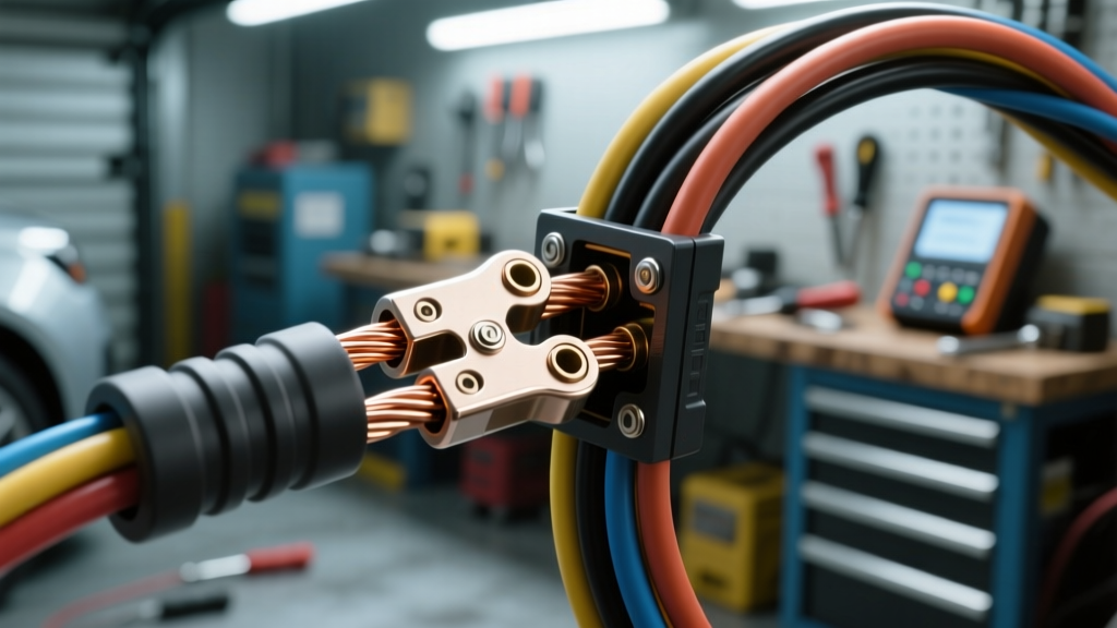
For our 18 AWG Yellow wire under the dashboard, the Solder-Seal Heat Shrink T-Tap is the optimal wire tap splice connector. It utilizes a copper piercing saddle to make electrical contact, surrounded by a heat-activated solder ring and an outer layer of polyolefin adhesive-lined heat shrink.
Step 3: Diagram-Guided Physical Execution
With the schematic verified and the correct connector selected, proceed with the physical installation. Because we are working under the dash near the BCM, space is constrained. Follow these precise steps to ensure a factory-grade connection:
- Disconnect the Battery: Always disconnect the negative battery terminal and wait 3 minutes for the BCM capacitors to discharge before working near module connectors.
- Prepare the Main Harness: Do not strip the insulation off the 18 AWG Yellow wire. Instead, carefully peel back the harness loom and cloth tape (Tesa tape) to expose about 2 inches of the target wire. Clean the wire jacket with isopropyl alcohol to remove any dielectric grease or dirt.
- Prepare the Accessory Wire: Strip exactly 1/4 inch (6mm) of insulation from the end of your aftermarket telemetry module's power wire. If the accessory wire is smaller than 22 AWG, fold it over and crimp it slightly to ensure it fills the barrel of the tap connector.
- Seat the T-Tap: Open the saddle of the solder-seal wire tap splice connector. Lay the 18 AWG Yellow wire into the main channel. Ensure the wire sits flat against the copper piercing teeth. Snap the cap closed. You should hear an audible click, confirming the teeth have penetrated the GXL insulation and bitten into the copper strands.
- Insert and Crimp the Branch: Insert the stripped accessory wire into the open barrel end of the T-Tap. Using a ratcheting crimping tool (calibrated for insulated terminals), crimp the barrel tightly. The ratchet ensures the exact amount of pressure is applied without crushing the copper.
- Apply Heat: Using a digital heat gun set to 220°C (425°F), apply heat evenly to the heat shrink tubing. Start from the center and move outward. Watch for the solder ring to melt and flow around the piercing saddle, and ensure the adhesive sealant oozes slightly from both ends of the tubing. This adhesive creates a waterproof barrier that prevents capillary action from drawing moisture into the harness.
Step 4: Verifying the Tap with a Multimeter
A schematic walkthrough is only as good as the physical verification that follows. Reconnect the battery and turn the ignition to the "Run" position (engine off).
Voltage Drop Testing
Set your digital multimeter to DC Volts. Place the red probe on the main harness side of the tap (piercing the wire jacket slightly upstream if necessary, or using a back-probe at the BCM X2 connector) and the black probe on the accessory side of your new wire tap splice connector. A healthy solder-seal tap should exhibit a voltage drop of less than 0.05V under load. If you measure a drop greater than 0.2V, the piercing teeth have not made adequate contact with the copper strands, or the crimp barrel is loose. In this case, the tap must be cut out, the damaged section of the 18 AWG wire removed, and an inline butt-splice used to repair the OEM harness before attempting a new tap.
Current Draw Verification
Finally, clamp a DC amp meter around the accessory wire to verify it is drawing the expected 3.5A. Cross-reference this with the wiring diagram's fuse rating one last time. By combining rigorous schematic analysis with high-quality solder-seal components, you ensure that your aftermarket integration is safe, reliable, and fully compliant with automotive electrical standards.