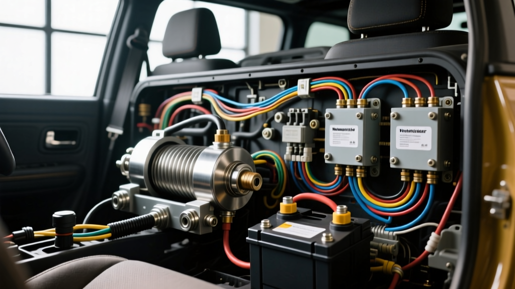
Project Scope: High-Draw 4x4 Accessory Integration
When tackling severe-duty 4x4 builds, executing a reliable auto electrical repair in Newburgh—or any region with harsh winter road treatments and extreme temperature fluctuations—requires far more than basic crimp connectors and electrical tape. High-amperage modifications, such as installing a 12,000 lb winch and a dual battery isolator system, push standard automotive charging systems to their absolute limits. Poorly executed wiring in these environments leads to catastrophic voltage drop, galvanic corrosion, and fried ECU modules due to inductive kickback.
This upgrade guide details the exact wiring procedures, connector types, and circuit protection methodologies required to safely integrate heavy-draw accessories into a modern vehicle's electrical architecture, ensuring compliance with SAE J1128 standards for low-voltage primary cables.
Bill of Materials & Wire Gauge Specifications
Undersized wiring is the leading cause of winch motor burnout and alternator failure. The following table outlines the mandatory specifications for a dual-battery and winch upgrade on a standard 12V automotive platform.
| Circuit Function | AWG Size | Wire Type | Connector / Termination | Circuit Protection |
|---|---|---|---|---|
| Winch Main Power Feed | 2 AWG | SGX (Cross-Linked) | 3/8' Ring Terminal (Hex Crimp) | 200A MEGA Fuse |
| Winch Main Ground | 2 AWG | SGX (Cross-Linked) | 3/8' Ring Terminal (Hex Crimp) | N/A (Chassis Ground) |
| Isolator Solenoid Load | 4 AWG | SGX (Cross-Linked) | 5/16' Ring Terminal | 150A MEGA Fuse |
| Solenoid Control Coil | 10 AWG | TXL (Thin-Wall) | Weather-Pack / Deutsch DT | 15A Mini Fuse |
| Accessory Aux Panel Feed | 8 AWG | TXL (Thin-Wall) | Anderson Powerpole 45A | 40A MAXI Fuse |
Phase 1: 2 AWG Winch Power Routing & Termination
The winch power circuit experiences massive transient current spikes, often exceeding 350 amps under peak stall loads. Standard PVC wire insulation will melt, and standard copper will suffer severe voltage drop over long chassis runs. You must use SGX (Specialty Grade Cross-Linked) wire, which withstands under-hood temperatures up to 125°C and resists battery acid and road salt.
Hex Crimping vs. Indent Crimping for High Amperage
For 2 AWG and 4 AWG high-current circuits, never use mechanical indent crimpers or hammer-style crimp tools. Indent crimps create high-resistance points and can slice through the copper strands, reducing the effective wire gauge and creating a localized hot spot. Instead, use a hydraulic crimper with a matched hexagonal die. The hex crimp uniformly compresses the copper barrel around the wire strands, creating a cold-weld gas-tight seal that minimizes millivolt drop across the termination.
- Strip the SGX Wire: Use a rotary wire stripper to remove exactly 7/8' of insulation. Do not nick the outer strands.
- Insert and Crimp: Insert the wire fully into the tinned copper 3/8' ring terminal. Cycle the hydraulic hex crimper until the dies fully close and the ratchet releases.
- Seal with Adhesive Heat Shrink: Slide a piece of 3:1 ratio, dual-wall marine heat shrink over the barrel. Apply heat evenly until the inner adhesive lining melts and extrudes slightly from the edges, completely sealing out moisture and preventing under-insulation corrosion.
- Torque Specifications: When securing the 3/8' terminal to the battery side-post or winch contactor, torque the M8 stainless steel hardware to exactly 10-12 Nm (8-10 ft-lbs). Over-torquing will strip the soft lead battery posts or warp the copper terminal, reducing surface contact area.
Phase 2: Continuous Duty Solenoid & Dual Battery Isolator
A common and disastrous mistake in auto electrical repair is using a standard 5-pin Bosch-style automotive relay to isolate a secondary battery. Standard relays are designed for intermittent duty; leaving the coil energized for hours while off-roading will overheat the coil windings, melt the plastic housing, and short the control circuit.
For a dual battery setup, you must install a Continuous Duty Solenoid (such as the Cole Hersee 24063 or equivalent Littelfuse heavy-duty solenoid). These solenoids feature a laminated steel core and copper windings designed to dissipate heat indefinitely while energized.
Solenoid Pinout and Control Circuit Wiring
| Terminal ID | Function | Wire Size | Connection Point |
|---|---|---|---|
| 30 (Input) | Main Battery Load | 4 AWG SGX | Primary Battery Positive (via 150A MEGA Fuse) |
| 87 (Output) | Secondary Battery Load | 4 AWG SGX | Secondary Battery Positive |
| 85 (Coil Ground) | Control Circuit Ground | 10 AWG TXL | Clean Chassis Ground / ECU Trigger Ground |
| 86 (Coil Power) | Control Circuit Ignition | 10 AWG TXL | Ignition-Run Fuse Box Circuit (via 15A Fuse) |
Pro-Tip for Modern CAN Bus Vehicles: Modern vehicles (2015+) utilize smart alternators and complex CAN bus networks that monitor battery voltage. Tapping directly into the ignition switch for terminal 86 can trigger parasitic draws or ECU fault codes. Instead, use an automotive-grade voltage sensing relay (VSR) or a CAN-safe ignition tap module to trigger the 10 AWG control circuit only when the alternator output exceeds 13.3V.
Phase 3: CAN Bus Protection & Flyback Diodes
When a heavy-duty solenoid or winch contactor disengages, the collapsing magnetic field in the coil generates a massive reverse-voltage spike (inductive kickback), often exceeding 400V for a fraction of a millisecond. In older vehicles, this caused minor radio static. In modern vehicles, this spike travels back down the 10 AWG control wire and instantly fries the Body Control Module (BCM) or the alternator's internal voltage regulator diode bridge.
The Fix: You must install a flyback diode (such as a 1N5408, 3A 1000V diode) across the solenoid coil terminals (85 and 86). The diode's cathode (silver stripe) must face the positive 12V trigger source (Terminal 86). This creates a closed loop that safely dissipates the inductive spike back into the solenoid coil as heat, completely protecting the vehicle's sensitive CAN bus and automotive circuit protection modules.
Diagnostic Troubleshooting: Voltage Drop Testing
After completing the physical wiring and connector terminations, you must verify circuit integrity under load using a digital multimeter (DMM) set to DC Millivolts (mV). A healthy high-amperage circuit should exhibit minimal resistance.
- Across the MEGA Fuse: Under a 50A simulated load, voltage drop should not exceed 15mV. Higher readings indicate internal fuse element degradation or poor bolt torque on the fuse block busbars.
- Across the Solenoid Contacts (30 to 87): When energized, the internal copper disc should bridge the contacts with a drop of less than 50mV. A reading over 150mV indicates pitted internal contacts requiring immediate solenoid replacement.
- Across the 2 AWG Cable Run: Measure from the battery post to the winch contactor stud. Acceptable drop is under 0.5V (500mV) at 100A. If voltage drop is excessive, check for undersized wire, improper hex crimps, or hidden corrosion beneath the heat shrink.
By adhering to these stringent wire gauge specifications, termination protocols, and circuit protection methodologies, your high-draw modifications will survive the harshest environments. Whether you are performing an intricate auto electrical repair in Newburgh to combat winter salt intrusion, or building a desert expedition rig, these principles ensure your electrical system remains robust, safe, and highly reliable.