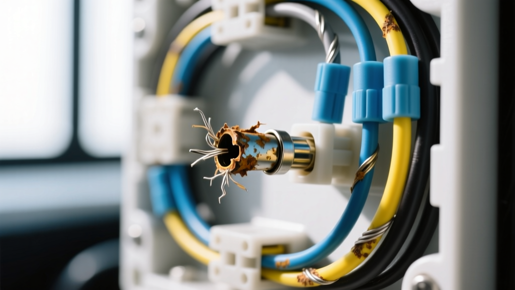
Introduction to Butt Splice Wire Connector Failures
The butt splice wire connector is a staple in automotive electrical repair, utilized for joining two lengths of wire end-to-end. When executed correctly, it provides a gas-tight, mechanically robust, and electrically conductive joint. However, in the harsh environment of a vehicle—characterized by constant vibration, thermal cycling, and exposure to corrosive elements—a poorly executed butt splice wire connector is a leading cause of parasitic draws, intermittent sensor faults, and high-resistance circuit failures. Troubleshooting these failures requires a systematic approach rather than guesswork. This guide provides a definitive, step-by-step troubleshooting flow to isolate, diagnose, and properly repair compromised butt splices in automotive wiring harnesses.
Step 1: Visual and Physical Inspection (The 'Tug and Look' Test)
Before reaching for a multimeter, a thorough physical inspection of the suspected butt splice wire connector is mandatory. Many catastrophic failures are immediately visible to the trained eye. Begin by tracing the harness to the splice location, often found near aftermarket accessory installations, repaired sensor pigtails, or grounding points.
- Insulation Integrity: If using heat-shrink variants, check for gaps at the barrel ends. The adhesive-lined polyolefin should show a slight bead of melted sealant at the edges. If the tubing is cracked, loose, or shows signs of charring, moisture ingress is highly likely.
- The 'Bellmouth' Check: A proper crimp leaves a slight 'bellmouth' at the front and rear of the metal barrel. If the wire is flush with the edge of the barrel, the wire was stripped too short, reducing the conductive surface area.
- Strand Visibility: You should see 1-2mm of bare copper wire protruding slightly past the metal crimp barrel before the insulation grip begins. If no copper is visible, the wire was stripped too long, creating a short-circuit hazard.
- Physical Pull Test: Grip the wire on both sides of the splice and apply firm, steady outward tension. A correctly crimped 12 AWG butt splice wire connector should withstand over 40 lbs of pull force before failure. If the wire slips or pulls out under light hand tension, the crimp die was incorrect or the tool lacked a ratcheting mechanism.
Step 2: Multimeter Voltage Drop Testing (The Definitive Diagnostic)
Resistance testing with an ohmmeter on a disconnected circuit is highly unreliable for diagnosing a failing butt splice wire connector, as standard DMMs cannot supply enough current to reveal micro-fractures or corrosion inside the crimp barrel. The industry standard diagnostic is the Voltage Drop Test performed on a live, loaded circuit.
- Turn the ignition ON and activate the circuit (e.g., command the cooling fan relay or turn on the headlights) to place the circuit under a physical load.
- Set your Digital Multimeter (DMM) to DC Volts.
- Place the red probe on the bare copper wire on the power source side of the butt splice.
- Place the black probe on the bare copper wire on the load side of the butt splice.
- Read the voltage drop. A healthy butt splice wire connector will drop less than 0.02V (20mV). Anything above the thresholds listed below indicates high internal resistance requiring immediate repair.
| Circuit Type | Typical AWG Size | Max Voltage Drop (Loaded) | Common Automotive Application |
|---|---|---|---|
| Low Current / Sensor | 20 - 16 AWG | 0.05V (50mV) | O2 Sensor signal, CAN bus lines |
| Medium Current / Actuator | 14 - 12 AWG | 0.10V (100mV) | Fuel injectors, cooling fans, relays |
| High Current / Power | 10 - 8 AWG | 0.15V (150mV) | Aftermarket fuel pumps, amplifiers, winches |
Step 3: Thermal Imaging Diagnostics
When a butt splice wire connector suffers from internal corrosion or a loose crimp, the increased electrical resistance generates heat as current passes through it (Joule heating). Using an automotive-grade thermal imaging camera (such as a FLIR C5 or similar), scan the harness while the circuit is under maximum load. A healthy splice will match the ambient temperature of the surrounding wire insulation. A failing splice will present as a distinct 'hot spot,' often showing a temperature delta (ΔT) of 10°C to 30°C above the baseline wire temperature. This is particularly useful for locating hidden splices wrapped in corrugated loom or electrical tape without stripping the entire harness.
Step 4: Common Failure Modes & Root Cause Decision Tree
Once a faulty butt splice wire connector is isolated via voltage drop or thermal testing, use this decision tree to identify the root cause before attempting a repair. Fixing the symptom without addressing the root cause will result in repeat failures.
Symptom A: Wire Pulls Out Under Light Tension
- Cause 1: Used non-ratcheting pliers instead of a dedicated ratcheting crimper. Fix: Always use a ratcheting tool that ensures the full crimp cycle is completed before releasing.
- Cause 2: Incorrect crimp die selection (e.g., using the red die for a 12 AWG blue wire). Fix: Match the die strictly to the wire gauge, not just the insulation color, as aftermarket wire insulation thickness varies.
Symptom B: High Voltage Drop / Intermittent Operation
- Cause 1: Oxidation or galvanic corrosion inside the barrel. Often seen when a non-sealed vinyl-insulated splice is used in a high-moisture area (e.g., wheel well or engine bay). Fix: Replace with an adhesive-lined, marine-grade heat shrink butt splice.
- Cause 2: 'Cold Crimp' where the wire strands were not compressed enough to break the copper oxide layer on the individual strands. Fix: Verify crimper calibration and ensure wire strands are twisted tightly before insertion.
Symptom C: Melted Insulation or Discolored Copper
- Cause 1: Over-crimping. Using a die that is too small cuts into the copper strands, reducing the cross-sectional area and creating a bottleneck for current flow, leading to extreme heat. Fix: Use a micrometer to verify wire diameter and select the correct AWG die.
- Cause 2: Using a standard lighter or open flame to shrink the tubing, which melts the inner wire insulation and compromises the copper. Fix: Use a variable-temperature heat gun set to approximately 250°C (480°F).
Step 5: Proper Repair and Rework Procedure
To properly repair a failed butt splice wire connector, you must completely remove the damaged section and start with virgin copper. Never attempt to re-crimp over an existing failed crimp.
- Excision: Use flush cutters to snip the wire at least 1 inch on either side of the failed splice to remove any work-hardened or stretched copper.
- Stripping: Use a precision wire stripper (not a knife, which can nick the strands and create a future break point). Strip the insulation to the exact length specified in the reference chart below.
- Insertion: Insert the stripped wire into the metal barrel. Ensure the wire bottoms out and protrudes slightly (approx. 1mm) from the opposite end of the metal barrel.
- Crimping: Place the connector into the correctly sized die of a ratcheting crimper. Squeeze until the tool releases. The insulation grip should securely hold the wire jacket, while the wire grip deforms the metal barrel into a tight 'B' or 'M' shape around the copper strands.
- Sealing: Apply heat evenly from the center of the heat shrink tubing outward toward the edges. Stop when the adhesive sealant purges slightly from the ends, indicating a complete environmental seal.
| Wire Gauge (AWG) | Standard Insulation Color | Strip Length (Inches) | Crimp Die Size | Pull-Out Force Minimum |
|---|---|---|---|---|
| 22 - 18 AWG | Red | 0.25' (6.4mm) | Red / 1.5mm² | 20 lbs |
| 16 - 14 AWG | Blue | 0.31' (8.0mm) | Blue / 2.5mm² | 30 lbs |
| 12 - 10 AWG | Yellow | 0.37' (9.5mm) | Yellow / 6.0mm² | 40 lbs |
| 8 AWG | Uninsulated / Large | 0.50' (12.7mm) | #8 Hex / 10mm² | 70 lbs |
Authoritative Sources & Standards
Proper termination of a butt splice wire connector is governed by strict automotive and aerospace engineering standards. The procedures and specifications outlined in this troubleshooting flow are derived from the following industry authorities:
- SAE J1128: The Society of Automotive Engineers standard for Low Tension Primary Cable, which dictates the physical properties, insulation thickness, and temperature ratings of the automotive wire being spliced. Read more at SAE International.
- IPC/WHMA-A-620: The definitive industry standard for Requirements and Acceptance for Cable and Wire Harness Assemblies. This document provides the exact visual criteria for acceptable crimp profiles, bellmouth dimensions, and insulation clearance. Learn more about crimp standards at IPC.org.
- TE Connectivity / Delphi Automotive: Manufacturer application tooling guides for ratcheting crimp dies, which provide the specific pull-test force minimums and die-closure height tolerances referenced in the charts above.