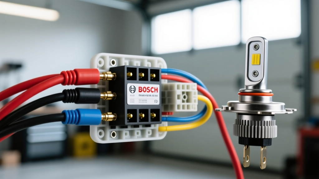
The Physics of Factory Wiring Failure
Upgrading to high-wattage H4 halogen bulbs or high-draw LED conversions often exposes the weak link in classic and economy vehicle electrical systems: the factory headlight wiring. Most OEM headlight circuits route 12V power from the battery, through the firewall, into the dashboard headlight switch, and back out to the front of the vehicle. This round-trip journey often exceeds 16 feet of 18 AWG or 16 AWG wire.
According to Ohm's Law, pushing 10 amps (the draw of a standard 55W H4 low beam) through 16 feet of thin factory wire results in a voltage drop of 1.2V to 1.5V. Because halogen filament output is exponentially tied to voltage, a 1.5V drop at the bulb translates to a massive 30% loss in usable light output, while simultaneously generating excess heat that melts OEM plastic connectors and dashboard switches. The definitive solution is bypassing the factory harness entirely by installing high-capacity car relays to create a dedicated, high-amperage power circuit directly from the battery to the headlights.
Required Materials and Wire Gauge Specifications
To build a reliable, fire-safe relay harness, you must use automotive-grade cross-linked wire (TXL or GXL) and proper sealed connectors. Never use household THHN wire or cheap vinyl electrical tape in an engine bay environment.
| Circuit Segment | Wire Gauge (AWG) | Insulation Type | Protection / Connector |
|---|---|---|---|
| Battery to Relay (Pin 30) | 10 AWG | TXL (Thin-Wall) | 30A MAXI Fuse, 3:1 Adhesive Heat Shrink |
| Relay to Headlights (Pin 87) | 12 AWG | TXL | H4 Ceramic Pigtails, Weather-Pack Seals |
| Factory Trigger to Relay (Pin 86) | 18 AWG | GXL | Posi-Tap or Solder/Sleeve |
| Relay Coil Ground (Pin 85) | 14 AWG | TXL | Ring Terminal, Star Washer to Chassis |
Standard ISO Mini Car Relays Pinout Reference
The automotive industry relies on the ISO Mini (commonly called 'Bosch-style') relay. These relays follow the DIN 72552 standard for terminal numbering. Understanding these pin numbers is critical for correct wiring.
- Pin 30 (Common): High-amp power input from the battery.
- Pin 87 (Normally Open): High-amp power output to the load (headlights).
- Pin 85 (Coil): Ground for the internal electromagnetic coil.
- Pin 86 (Coil): Switched 12V trigger input from the factory headlight switch.
Expert Note: If your car relays contain an internal flyback suppression diode (often marked on the relay casing), polarity matters. Pin 86 must receive the positive 12V trigger, and Pin 85 must go to ground. Reversing these will cause a dead short through the diode, instantly blowing your trigger circuit fuse.
Step-by-Step H4 Headlight Relay Installation
Step 1: Routing the High-Amp Power Feed
Begin by measuring the distance from the positive battery terminal to the relay mounting location near the front core support. Cut a length of 10 AWG TXL wire. Install a 30A MAXI fuse holder within 6 inches of the battery positive terminal—this is a non-negotiable SAE safety requirement to prevent harness fires in the event of a short. Crimp a 10 AWG ring terminal using an open-barrel crimping tool, and secure it to the battery. Route the wire along the factory wiring loom, securing it with UV-resistant zip ties and split-loom tubing to protect against abrasion and exhaust heat.
Step 2: Tapping the Factory Trigger Circuit
Unplug the factory H4 connector from the driver-side headlight. Identify the low-beam trigger wire using a digital multimeter (it will show 12V when the headlights are switched on). Instead of using 'Scotch-Lok' piercing taps—which strand copper wire and invite corrosion—use a Posi-Tap connector or strip the wire, solder an 18 AWG tap, and seal it with adhesive-lined heat shrink. Run this 18 AWG trigger wire to Pin 86 on your relay.
Step 3: Wiring the Load Circuit to the Headlights
Connect the 10 AWG power feed to Pin 30 on the relay. From Pin 87, run a 12 AWG wire to a sealed distribution block or directly to the H4 ceramic pigtails at the headlights. Because you are bypassing the factory ground, you must run a dedicated 12 AWG ground wire from the H4 pigtail grounds directly to a clean, unpainted chassis point or back to the negative battery terminal. This 'dedicated ground' topology ensures the headlights receive a full 14.2V (alternator voltage), maximizing lumen output.
Step 4: Establishing a Clean Chassis Ground
Pin 85 requires a solid ground to energize the coil. Locate a factory grounding bolt on the inner fender or core support. Remove the bolt, clean the metal surface with a wire wheel to bare steel, and attach a 14 AWG ring terminal. Reinstall the bolt with a star washer to bite through any future surface oxidation, ensuring a permanent low-resistance path to the battery negative.
Modern Vehicle Considerations: CAN-Bus and BCM Protection
If you are installing car relays on a modern vehicle (typically 2008 and newer) where the Body Control Module (BCM) drives the headlights via solid-state transistors or Pulse Width Modulation (PWM), you must protect the BCM. When a relay coil de-energizes, it generates a high-voltage inductive kickback spike (often exceeding 100V). While a factory mechanical switch can absorb this arc, a delicate BCM transistor will be destroyed by it.
To prevent this, solder a 1N4001 flyback diode across the relay coil pins (85 and 86). The diode's silver stripe must face Pin 86 (the positive trigger side). This creates a localized loop that safely dissipates the inductive spike back into the coil, protecting your vehicle's expensive computer modules. For deeper insights into BCM-safe relay wiring, refer to the technical bulletins provided by Daniel Stern Lighting Consultancy.
Real-World Failure Modes and Troubleshooting Matrix
Even with premium car relays, installation errors can cause erratic behavior. Use this diagnostic matrix to troubleshoot common issues:
| Symptom | Probable Cause | Diagnostic Fix |
|---|---|---|
| Relay clicks rapidly (chatters) | Voltage drop on the 18 AWG trigger wire, or factory ground is floating. | Measure trigger voltage at Pin 86 with lights ON. If below 11.5V, upgrade trigger wire or add a secondary ground to the factory plug. |
| Relay clicks, but lights are dim | High resistance on Pin 30 power feed or poor chassis ground on headlight pigtail. | Perform a voltage drop test across the 30-to-87 circuit. Clean chassis ground points with sandpaper. |
| Lights stay ON when car is off | Relay installed backward (Pins 30 and 87 swapped) or internal relay contacts welded shut. | Verify Pin 30 is hot at all times and Pin 87 is only hot when energized. Replace relay if welded. |
| BCM throws 'Bulb Out' dashboard warning | The relay coil draws only ~150mA, whereas the BCM expects a 55W bulb (4.5A) draw. | Install a 50W/6-ohm power resistor in parallel with the relay coil, or use a CAN-bus compatible PWM decoder module. |
Authoritative References
- SAE International - SAE J1128: Low Tension Primary Cable Standard (Defines TXL/GXL wire insulation requirements for engine bay heat resistance).
- Painless Performance Products - Relay Harness Installation Manual (Industry standard routing and fusing topologies for high-amp automotive lighting).
- Daniel Stern Lighting - Automotive Relay Technical Guide (Advanced DIN 72552 pinout analysis and flyback diode implementation).