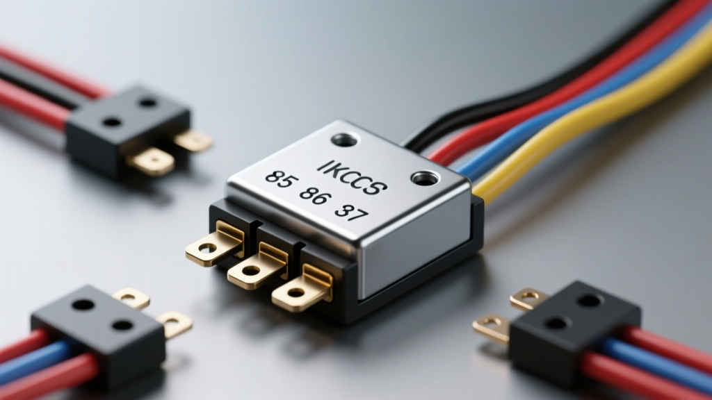
The Core Concept: Why We Use Relays in Automotive Wiring
When tackling aftermarket lighting installations, headlight upgrades, or auxiliary power circuits, understanding how does a car relay work is the single most important fundamental you can master. At its core, an automotive relay is an electromagnetic switch. It allows a low-current, low-amperage circuit (like your dashboard switch or a factory BCM signal) to safely control a high-current, high-amperage circuit (like a 120W LED light bar or off-road driving lamps).
Without a relay, routing high current directly through a dashboard switch would require massive, heavy-gauge wires running through the firewall and into the cabin. This creates a severe fire hazard and voltage drop. By using a relay, you keep the heavy-gauge wiring under the hood, directly between the battery and the load, while only sending a tiny trigger current into the cabin.
How Does a Car Relay Work? The Physics of the Electromagnetic Switch
To understand the internal mechanics, we look at the standard ISO Mini 4-pin relay (often referred to as a Bosch-style relay). Inside the sealed plastic or metal housing, there are two distinct circuits that never physically touch:
- The Coil Circuit (Electromagnet): When 12 volts is applied across the relay's electromagnetic coil, it generates a magnetic field.
- The Contact Circuit (The Switch): This magnetic field pulls a steel armature (a physical lever) downward. The armature bridges the gap between the high-current input and output terminals, allowing electricity to flow to your lights.
When you turn off the dashboard switch, the magnetic field collapses. A small return spring pushes the armature back to its resting position, breaking the high-current circuit and turning off the lights. According to Hella's technical relay documentation, this mechanical isolation is what protects delicate factory wiring harnesses and BCM (Body Control Module) outputs from melting under heavy auxiliary loads.
Decoding the ISO Mini 4-Pin Relay Pinout
Standard automotive relays use a universal numbering system stamped onto the base of the relay housing. Memorizing these four numbers is mandatory for any auto electrician. Here is the exact breakdown for a standard Normally Open (NO) 4-pin relay:
| Pin Number | Function | Standard Wire Color | Recommended AWG (Up to 20A) |
|---|---|---|---|
| 30 | Common Power Input (From Battery) | Red | 12 AWG or 10 AWG |
| 87 | Normally Open Output (To Load/Lights) | Red with White Stripe | 12 AWG or 10 AWG |
| 85 | Coil Ground | Black | 16 AWG or 18 AWG |
| 86 | Coil Power (Trigger from Switch) | Yellow or Switched Color | 16 AWG or 18 AWG |
Note: Pins 85 and 86 make up the low-current coil. While they are technically non-polarized on standard mechanical relays, if your relay contains an internal flyback diode or resistor (common in modern vehicles to protect the ECU), pin 85 must be grounded and pin 86 must receive the positive trigger.
Step-by-Step: Wiring a 120W LED Light Bar Using a 4-Pin Relay
Let's apply the theory to a real-world scenario. You are installing a 120W LED light bar on a 2018 Jeep Wrangler JL. Here is how to wire it safely using the correct automotive standards.
Step 1: Calculate the Load and Select the Fuse
First, determine the amperage draw of your light bar. Using Ohm's Law (Amps = Watts / Volts), we calculate 120W / 14.4V (alternator charging voltage) = 8.33 Amps. SAE standards dictate that a fuse should be rated at 125% to 150% of the continuous load. Therefore, 8.33A x 1.25 = 10.4A. You should use a 15A ATO blade fuse on the main power wire to protect the circuit without nuisance blowing.
Step 2: Route and Crimp the High-Current Circuit (Pins 30 & 87)
- Pin 30 (Battery Power): Run a 12 AWG red wire from the positive battery terminal. Install an inline 15A fuse holder within 6 inches of the battery post. Terminate this wire with a heat-shrink ring terminal and secure it to the relay's Pin 30 spade.
- Pin 87 (Load Power): Run a 12 AWG red/white wire from Pin 87 directly to the positive input of your LED light bar. Use a weather-sealed Deutsch DT connector at the light bar to prevent moisture ingress and corrosion.
- Grounding the Load: Run a 12 AWG black wire from the negative input of the light bar to a clean, bare-metal chassis ground. Always use a star washer to bite through the paint and ensure a zero-resistance ground.
Step 3: Wire the Low-Current Trigger Circuit (Pins 85 & 86)
- Pin 85 (Coil Ground): Run an 18 AWG black wire from Pin 85 to a local chassis ground under the hood.
- Pin 86 (Coil Trigger): Run an 18 AWG yellow wire from Pin 86, through the firewall via an existing rubber grommet, and into the cabin. Connect this to your dashboard-mounted rocker switch. The other side of your rocker switch should be wired to a fused ignition-switched 12V source (so the light bar cannot be accidentally left on and drain the battery).
Real-World Failure Modes and Advanced Troubleshooting
Even high-quality Littelfuse or Bosch automotive relays can fail if installed incorrectly. Here are the most common failure modes encountered in the field:
1. Contact Pitting and Inductive Kickback
When a relay switches off an inductive load (like halogen bulbs or older ballasts), the collapsing magnetic field in the load creates a massive reverse voltage spike, sometimes exceeding 100V for a microsecond. This causes an electrical arc across the relay's internal contacts (Pins 30 and 87). Over time, this arc melts the metal, causing contact pitting. The relay eventually welds itself shut (lights stay on permanently) or develops high resistance (lights flicker). Fix: Use relays with built-in resistors or add an external flyback diode across the load.
2. Voltage Drop and Relay Chatter
If your wire gauge is too small, or your ground connections are corroded, the voltage reaching the relay coil (Pins 85/86) will drop. A standard 12V relay requires at least 9V to pull the armature in securely. If voltage drops to 7V under load, the magnetic field weakens, the spring pushes the armature back, the voltage recovers, and the relay pulls in again. This rapid on-off cycle is called "chatter" and will destroy your light bar's internal drivers. Fix: Always measure voltage drop across the coil while the circuit is active using a Digital Multimeter (DMM).
Testing Your Relay with a Digital Multimeter (DMM)
Before throwing away a suspect relay, bench-test it to confirm the failure:
- Test the Coil (Pins 85 & 86): Set your DMM to Ohms (Resistance). Place probes on 85 and 86. A healthy coil will read between 60 and 90 ohms. If it reads OL (Open Line), the internal copper wire is broken.
- Test the Contacts (Pins 30 & 87): Set your DMM to Continuity or Ohms. Place probes on 30 and 87. It should read OL (no connection). Now, use a jumper wire to apply 12V and Ground to pins 86 and 85. You should hear a distinct "click." The DMM should now read less than 0.05 ohms. If it reads higher, the internal contacts are pitted and the relay must be replaced.
Mastering these fundamentals ensures your aftermarket lighting installations are safe, reliable, and compliant with standard automotive electrical practices.