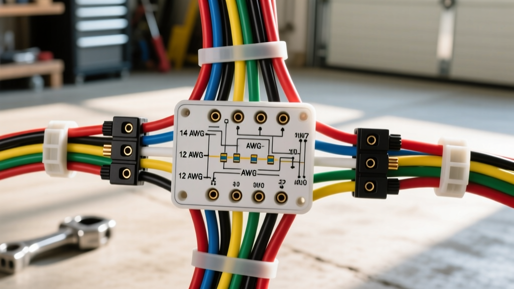
Introduction to Trailer Brake Installation Faults
Installing an aftermarket electric brake controller—such as a Tekonsha Prodigy P3 or Redarc Tow-Pro Elite—transforms a standard tow vehicle into a capable heavy-hauler. However, the process is rarely as simple as plugging in a harness. When you first connect your trailer and the controller display throws an error code, or the brakes fail to engage proportionally, you are faced with the complex task of troubleshooting electric trailer brake problems. These issues usually stem from improper wire gauge selection, voltage drop across long runs, or poor chassis grounding rather than a faulty controller unit.
This practical installation and diagnostic guide bridges the gap between physical wiring and electronic fault-finding. We will cover the SAE standard 7-way RV blade connector, brake controller pigtail routing, and systematic multimeter testing to isolate faults between the tow vehicle, the umbilical cord, and the trailer brake magnets.
The 7-Way RV Blade Connector: Pinout and Wire Gauge Specs
Before diagnosing a fault, you must verify that the tow vehicle's 7-way receptacle and the trailer's 7-way plug are wired identically and utilizing the correct American Wire Gauge (AWG) to handle the amperage. According to the SAE J286 Trailer Connector Standard, the pinout and minimum wire gauges for a standard RV blade connector are as follows:
| Clock Position | Function | Wire Color | Minimum AWG | Max Amperage |
|---|---|---|---|---|
| 7:00 (Bottom Center) | Ground (White) | White | 8 AWG | 40A+ |
| 11:00 (Top Left) | Tail / Running Lights | Brown | 12 AWG | 15A |
| 9:00 (Middle Left) | Left Turn / Stop | Yellow | 12 AWG | 15A |
| 1:00 (Top Right) | 12V Auxiliary Power | Black | 10 AWG | 30A |
| 3:00 (Middle Right) | Right Turn / Stop | Green | 12 AWG | 15A |
| 5:00 (Bottom Right) | Electric Brakes | Blue | 10 AWG | 30A |
| 7:00 (Bottom Left) | Reverse Lights / Aux | Purple | 12 AWG | 15A |
Installation Note: For trailers exceeding 25 feet in length, voltage drop becomes a critical factor. The etrailer Wiring FAQ highly recommends upsizing the Blue (Brakes) and White (Ground) wires to 8 AWG for long umbilical runs to ensure the brake magnets receive a full 12 volts under heavy load.
Brake Controller Pigtail: Routing and Connection
Most universal brake controllers utilize a 4-wire pigtail. Misrouting or misidentifying these wires during installation is the primary cause of controller failure or blown vehicle fuses.
- White (Ground): Must be routed directly to the vehicle's negative battery terminal or a dedicated, bare-metal chassis ground point. Never ground this to a painted surface or share it with a high-draw accessory ground.
- Black (12V Power): Routes to the positive battery terminal. CRITICAL: This wire must be protected by a 30A Maxi-fuse or a 30A auto-reset circuit breaker installed within 18 inches of the battery positive post to prevent catastrophic harness fires in the event of a dead short.
- Red (Stoplight Switch): Connects to the 'cold' side of the vehicle's brake pedal stoplight switch. This wire should only read 12V when the brake pedal is physically depressed. Connecting it to the 'hot' (constant 12V) side will cause the trailer brakes to lock up whenever the ignition is on.
- Blue (Brake Output): Routes through the firewall (using a sealed rubber grommet and dielectric silicone sealant) to Pin 6 (5 o'clock) on the 7-way receptacle.
Symptom-Cause-Fix Decision Tree for Installation Faults
When troubleshooting electric trailer brake problems immediately following an install, use this decision matrix to isolate the fault based on the controller's digital display or physical behavior.
| Symptom / Error Code | Probable Cause | Corrective Action |
|---|---|---|
| 'S.H.' (Short Circuit) - Displayed when no trailer is connected. | Blue output wire is pinched against the chassis or touching the ground wire inside the 7-way plug. | Inspect the 7-way receptacle for bent pins. Check the Blue wire routing under the dash and through the firewall for stripped insulation. |
| 'P.L.' (Poor Ground) - Displayed when trailer is connected. | Insufficient ground path between the tow vehicle and the trailer chassis. | Upgrade the 7-way White wire to 8 AWG. Sand the trailer chassis ground point to bare metal and apply anti-oxidant paste. |
| Brakes lock up when headlights are turned on. | Ground backfeed. The trailer's running lights are seeking a ground through the brake circuit due to a corroded trailer ground. | Clean the main trailer tongue ground. Verify the Brown (tail) wire is not shorted to the Blue (brake) wire in the trailer junction box. |
| Controller is completely dead (No display). | Blown 30A inline fuse on the Black power wire, or White ground wire is disconnected. | Test voltage at the controller's Black wire with a DMM. If 0V, replace the inline fuse and check for a short to ground. |
Isolating the Fault: Vehicle vs. Trailer
A common pitfall when troubleshooting electric trailer brake problems is assuming the fault lies with the tow vehicle's new installation when the issue is actually inside the trailer's wheel hubs or breakaway switch.
Testing the Breakaway Switch
The trailer breakaway switch pulls 12V directly from the trailer's auxiliary battery and feeds it down the Blue wire to the magnets if the trailer separates. If this switch is wired incorrectly, or if the internal plunger is stuck, it will backfeed voltage into the brake controller, triggering an 'S.H.' (Short) or 'C.' (Connection) error.
- Unplug the 7-way umbilical from the tow vehicle.
- Remove the breakaway pin from the trailer switch.
- Set your Digital Multimeter (DMM) to DC Volts.
- Probe the Blue wire terminal on the trailer's 7-way plug and the White (Ground) terminal.
- If you read 12V with the 7-way unplugged, your breakaway switch is backfeeding the circuit or the trailer battery is wired incorrectly.
Verifying Brake Magnet Resistance
If the controller reads 'C.' (Connected) but braking power is weak or non-existent, you must verify the physical brake magnets. According to Tekonsha Installation Guides, a standard 10-inch or 12-inch electric brake magnet should exhibit a resistance of roughly 3.2 to 3.6 ohms.
- Set your DMM to Ohms (Ω).
- Disconnect the two magnet wires inside the trailer's wheel hub backing plate.
- Place one probe on each magnet wire terminal.
- Reading ~3.5 Ω: Magnet is healthy.
- Reading 0 Ω or Continuity: Internal short; magnet must be replaced.
- Reading Infinite (OL): Open circuit; the coil wire is broken inside the magnet housing.
Voltage Drop Testing the Brake Circuit
If the controller outputs 100% power but the trailer brakes feel weak, you are likely suffering from voltage drop due to undersized wiring or high resistance at connection points. A voltage drop test is the only definitive way to prove this.
- Connect the trailer to the tow vehicle and turn on the ignition (engine off to prevent alternator noise).
- Manually slide the brake controller override lever to 100% output.
- Set your DMM to DC Volts (20V scale).
- Place the Red probe on the positive terminal of the trailer's battery (or the main 12V feed at the trailer junction box).
- Place the Black probe on the Blue wire at the exact point it enters the trailer's brake magnet.
- Acceptable Drop: Less than 0.5V.
- Unacceptable Drop: Greater than 0.5V indicates high resistance. You must upgrade the trailer's internal Blue wire harness to 10 AWG or clean corroded butt-splices using heat-shrink terminals with integral solder rings.
Grounding Best Practices to Prevent Intermittent Faults
Over 70% of intermittent trailer lighting and braking issues are ground-related. The White ground wire carries the return current for every circuit on the trailer. When installing or repairing a 7-way harness, adhere to these strict grounding protocols:
- Ring Terminals: Use only closed-loop, heat-shrink ring terminals. Never use spade or fork terminals for the main ground, as vibration will inevitably loosen them.
- Surface Prep: Use a wire wheel or 80-grit sandpaper to remove all paint, powder coat, and rust down to bright, bare steel at the grounding point.
- Hardware: Use a Grade 8 bolt with a star washer (to bite into the bare metal) and a nylon-insert locknut to prevent vibration loosening.
- Corrosion Protection: After securing the ground, apply a liberal coating of dielectric grease or anti-oxidant paste over the terminal to block moisture ingress.
- Torque Specifications: For a 10 AWG or 8 AWG ring terminal secured with a 1/4-inch bolt, torque the fastener to exactly 75-90 in-lbs. Over-torquing will snap the bolt; under-torquing will result in micro-arcing and eventual voltage drop.
Conclusion
Troubleshooting electric trailer brake problems during a fresh installation requires patience and a methodical approach. By verifying the SAE J286 7-way pinout, ensuring 10 AWG minimums on high-amperage circuits, and utilizing a DMM for voltage drop and resistance testing, you can eliminate guesswork. Always isolate the tow vehicle from the trailer to determine which side of the umbilical cord harbors the fault, and never compromise on the integrity of the main chassis ground.