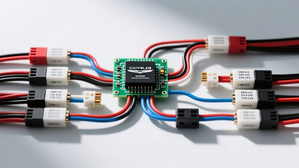
LX Platform Electrical Architecture Overview
The Chrysler 300, built on the LX platform, utilizes a highly multiplexed electrical architecture that relies heavily on the Totally Integrated Power Module (TIPM) and a dual-network Controller Area Network (CAN) bus system. When diagnosing Chrysler 300 electrical problems, technicians must move beyond standard 12V DC testing and understand module communication, solid-state power distribution, and network topology. Intermittent no-starts, phantom battery drains, and erratic accessory behavior are rarely caused by simple blown fuses; they are typically rooted in TIPM internal relay failures, CAN bus termination faults, or high-resistance ground paths.
Totally Integrated Power Module (TIPM) Failure Modes
Introduced in the 2007 model year, the TIPM replaced the traditional Integrated Power Module (IPM) and Front Control Module (FCM) setup. It acts as both a power distribution center and a gateway module. The most notorious of all Chrysler 300 electrical problems is the internal fuel pump relay failure within the TIPM (primarily affecting 2007-2013 models).
Internal Fuel Pump Relay Bypass Specifications
The TIPM utilizes a micro-relay soldered directly to the internal printed circuit board (PCB) to control the fuel pump. Over time, thermal cycling causes the solder joints to fracture, resulting in a crank-no-start condition. While replacing the TIPM is the OEM repair, a permanent and reliable field repair involves bypassing the internal relay using an external 30A ISO mini-relay.
- Power Source: Tap the B+ (Battery Positive) feed at the TIPM C1 connector or the jump-start stud using 10 AWG primary wire.
- Trigger Source: Use the Automatic Shutdown (ASD) relay output circuit. Locate the ASD output wire (typically Dark Green/Orange, DG/OR, 16 AWG) to ensure the fuel pump only runs when the PCM commands the ASD relay closed.
- Load Output: Splice into the fuel pump feed wire at TIPM Connector C7, Cavity 12 (typically Dark Green/Yellow, DG/YL, 14 AWG).
- Protection: Install an inline 30A MAXI fuse on the B+ feed leg within 6 inches of the power source.
TIPM Connector Pinout & Wire Gauge Reference
Proper voltage drop testing at the TIPM requires knowing the exact pinouts and expected wire gauges. A voltage drop exceeding 0.2V across any power distribution cavity under load indicates internal TIPM bus bar corrosion.
| Connector | Cavity | Wire Color | AWG | Circuit Function |
|---|---|---|---|---|
| C1 | 1 | Red/Light Green (RD/LG) | 2 AWG | Direct B+ Battery Feed (Main) |
| C3 | 14 | Pink/Yellow (PK/YL) | 16 AWG | Ignition Run/Start Feed |
| C7 | 12 | Dark Green/Yellow (DG/YL) | 14 AWG | Fuel Pump Module Supply |
| C7 | 28 | Dark Green/Orange (DG/OR) | 16 AWG | ASD Relay Output (PCM Feed) |
CAN Bus Network Topology and Diagnostics
The Chrysler 300 utilizes two primary CAN networks: the High-Speed CAN-C (drivetrain and chassis modules) and the Interior High-Speed (CAN-IHS) network (infotainment, HVAC, and body control). Network communication faults trigger a cascade of U-codes (e.g., U0100, U0140) and cause the Electronic Throttle Control (ETC) warning light to illuminate.
CAN-C vs. CAN-IHS Wire Colors and Pins
When diagnosing communication dropouts at the Data Link Connector (DLC), technicians must verify the physical layer integrity. According to SAE J2284 standards for high-speed CAN, the physical layer requires precise twisted-pair routing and termination.
| Network | DLC Pin | Signal | Wire Color (Typical LX) | Voltage (Idle) |
|---|---|---|---|---|
| CAN-C | 6 | CAN-High | Dark Green/White (DG/WT) | 2.5V - 3.5V |
| CAN-C | 14 | CAN-Low | Dark Green/Orange (DG/OR) | 1.5V - 2.5V |
| CAN-IHS | 3 | CAN-High | White/Violet (WT/VT) | 2.5V - 3.5V |
| CAN-IHS | 11 | CAN-Low | White/Dark Green (WT/DG) | 1.5V - 2.5V |
Terminating Resistor Verification
A frequent cause of Chrysler 300 electrical problems involving multiple module dropouts is a failed terminating resistor. The CAN-C bus requires two 120-ohm terminating resistors located at opposite ends of the network (typically inside the PCM and the TIPM or ABS module).
Diagnostic Step: With the vehicle powered OFF and the battery disconnected, set your multimeter to Ohms. Measure across DLC Pin 6 and Pin 14. You should read exactly 60 ohms (the parallel equivalent of two 120-ohm resistors). If you read 120 ohms, one terminating resistor is open. If you read near 0 ohms, the CAN-High and CAN-Low circuits are shorted together, often due to chafing in the main harness where it passes through the firewall bulkhead connector.
For deeper diagnostic strategies on multiplexed networks, the AA1CAR CAN Bus Diagnostic Guide provides excellent oscilloscope waveform references for identifying skewed bias voltages caused by failing transceivers.
Ground Distribution and Voltage Drop Testing
The LX platform is notoriously sensitive to poor ground connections. Modules share ground splices, and a corroded ground stud will cause back-feeding through the CAN bus, leading to bizarre symptoms like the headlights flashing when the power window switch is pressed. Always perform a voltage drop test on the ground side of the circuit under load before replacing modules.
Primary Ground Stud Locations and Torque Specs
When cleaning or re-terminating ground eyelets, use a wire brush to remove corrosion down to bare metal, apply dielectric grease to prevent future oxidation, and adhere strictly to factory torque specifications to prevent stripping the aluminum body studs.
| Ground ID | Location | Stud Size | Torque Spec | Primary Modules Served |
|---|---|---|---|---|
| G100 | Left Front Strut Tower | M8 | 20 Nm (15 lb-ft) | PCM, TCM, ABS Module |
| G200 | Right Front Strut Tower | M8 | 20 Nm (15 lb-ft) | Engine Harness, Injectors, Coils |
| G300 | Left Kick Panel (A-Pillar) | M6 | 10 Nm (89 lb-in) | CAN-IHS Splice, Instrument Cluster |
| G400 | Right Rear Wheel House | M8 | 20 Nm (15 lb-ft) | Fuel Pump Module, Rear Lighting |
Parasitic Draw Testing & The IOD Fuse
Diagnosing parasitic battery drain on a Chrysler 300 requires patience. The CAN-IHS bus can remain awake for up to 15 minutes after the ignition is turned off and the doors are locked. If you attempt to measure amperage before the modules enter sleep mode, you will see a draw of 1.5A to 3.0A, which is normal for the awake state.
The Ignition Off Draw (IOD) Fuse
To isolate the source of a parasitic draw, locate the IOD fuse in the TIPM. This is typically a 20A or 30A Pink cartridge fuse (cavity location varies by year, often Cavity 34 or 42). The IOD fuse cuts power to the CAN-IHS bus, the radio, and the interior lighting module.
Testing Procedure:
- Connect a multimeter (set to 10A) in series with the negative battery terminal.
- Close all doors, latch the hood switch manually, and lock the vehicle with the key fob.
- Wait 20 minutes for the CAN bus to fully power down.
- If the draw remains above 50mA, pull the IOD fuse in the TIPM.
- If the draw drops below 30mA, the fault lies in an interior module (e.g., a failing Bluetooth hands-free module or a stuck HVAC actuator keeping the bus awake).
- If the draw remains high, proceed to pull the CAN-C fuses and the PCM/ABS relays to isolate the high-speed network fault.
Authoritative References
For wiring diagrams, connector cavity views, and terminal repair kits, technicians should consult the Mopar Connection Repair System. Utilizing the correct wedge-lock terminals and sealed splices is critical when repairing the TIPM pigtails to prevent moisture ingress and subsequent copper verdigris buildup.