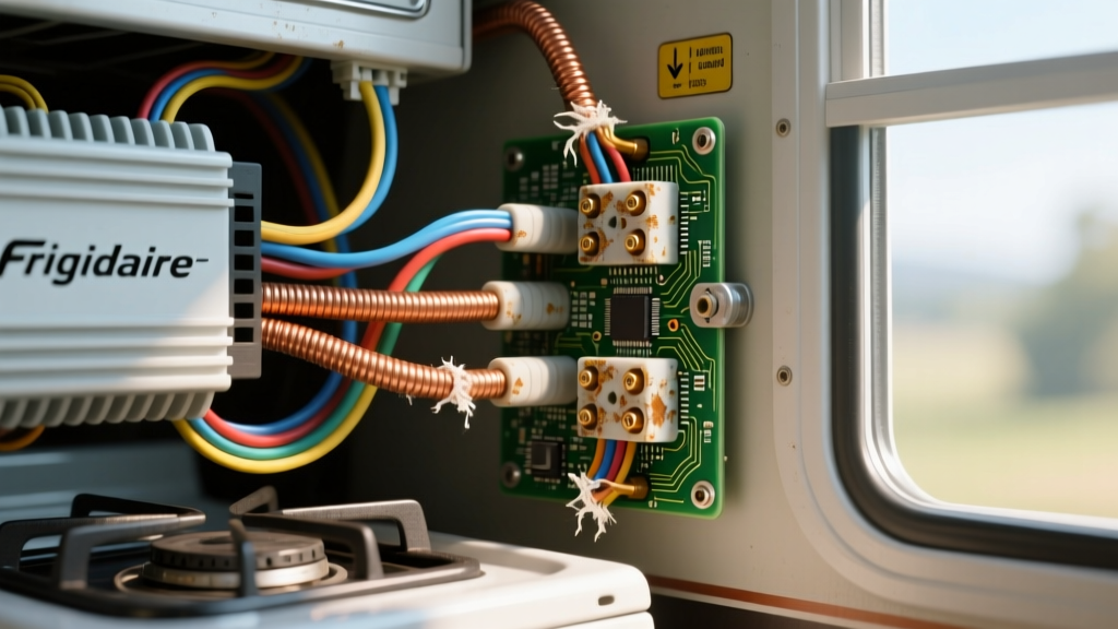
The Challenge of Residential Appliances in Mobile DC Chassis
When upfitting expedition vehicles, Sprinter camper vans, or heavy-duty truck chassis with mobile kitchens, integrators frequently bridge the gap between 12V/24V DC automotive systems and 120V AC residential appliances. A common scenario involves installing high-draw induction or electric radiant cooktops. However, when searching overland forums for 'frigidaire stove electrical problems', technicians often find that the root cause is rarely a defective appliance. Instead, the fault lies in mobile power delivery, specifically voltage sag, Total Harmonic Distortion (THD), and Electromagnetic Interference (EMI) inherent to improperly wired inverter systems.
Residential appliances are engineered for the stable, pure sine wave power of a municipal grid. When powered by a mobile inverter, the appliance's Electronic Smoothtop Element Control (ESEC) boards and microcontrollers become highly sensitive to the electrical noise and voltage fluctuations common in automotive environments. This guide provides a technical specification reference and diagnostic matrix to resolve these integration faults using automotive and marine electrical standards.
Decoding Appliance Faults: When the Wiring is the Culprit
Frigidaire electric stoves and cooktops utilize complex relay boards and capacitive touchpads. These components require a clean AC signal with a THD of less than 5%. If a Modified Sine Wave (MSW) inverter is used, or if a Pure Sine Wave (PSW) inverter is starved of DC current due to undersized cabling, the microcontroller will throw error codes that mimic component failure.
Common Error Codes Mapped to DC/AC Wiring Faults
- F10 (Runaway Temperature): On a residential grid, this indicates a failed temperature sensor or stuck relay. In an RV/Overland setup, this is frequently caused by severe DC voltage sag. When the heating element engages, it draws 1500W–2000W. If the DC wiring is undersized, voltage at the inverter drops below the low-voltage cutoff (LVC), causing the AC output to collapse. This sudden power loss can cause the appliance's mechanical relay to arc and weld shut. When the inverter recovers, the element receives continuous power, triggering the F10 safety code.
- E0E (Main Board Communication Error): This code signifies a loss of communication between the touchpad interface and the main relay board. In mobile builds, this is almost always caused by EMI. If high-amperage DC cables (carrying 150A+ pulsed DC) are routed parallel to the 120V AC appliance wiring without proper shielding or separation, the induced electromagnetic noise corrupts the low-voltage data bus inside the stove.
- F11 (Shorted Keypad): While humidity in a camper van can cause physical shorts, an F11 code on a dry day often points to a floating AC ground reference. If the inverter's neutral-ground bonding relay is malfunctioning or improperly configured, the capacitive touchpad loses its baseline voltage reference, registering phantom touches.
Technical Specification: Inverter-to-Appliance Wiring Matrix
To prevent the aforementioned frigidaire stove electrical problems, the DC supply side of the inverter must be sized not just for continuous amperage, but for the peak surge required when the appliance's control board initializes and the first heating element engages. The following matrix aligns with NFPA 1192 Standard on Recreational Vehicles and ABYC E-11 AC & DC Electrical Systems guidelines.
| Inverter Rating (W) | DC Cable Gauge (AWG) | Max DC Run (One Way) | DC Overcurrent Protection | AC Wire Gauge | AC Breaker Size |
|---|---|---|---|---|---|
| 2000W | 2/0 AWG | 5 ft (1.5m) | 250A ANL / Class T | 10 AWG | 20A GFCI |
| 3000W | 4/0 AWG | 5 ft (1.5m) | 400A Class T | 10 AWG | 30A GFCI |
| 5000W (24V) | 2/0 AWG (per leg) | 10 ft (3m) | 250A Class T | 8 AWG | 40A GFCI |
Diagnostic Decision Tree: Voltage Drop and Grounding
When faced with appliance faults, do not immediately replace the ESEC board or touchpad. Follow this systematic diagnostic tree to verify the automotive electrical infrastructure.
Step 1: The Dynamic DC Voltage Drop Test
Static voltage readings are useless for diagnosing high-draw appliance faults. You must measure voltage sag under load.
- Set your digital multimeter (e.g., Fluke 87V) to DC Volts and enable the MIN/MAX recording function.
- Connect the probes directly to the inverter's DC input lugs (not the battery terminals).
- Turn on the Frigidaire stove and set the highest wattage burner to maximum.
- Observe the MIN voltage reading. If the voltage at the inverter lugs drops below 10.5V (on a 12V system) or 21.0V (on a 24V system), the DC cabling is insufficient, or the battery bank's C-rate cannot support the surge. This voltage sag causes the inverter to clip the AC sine wave, generating massive THD and triggering appliance logic faults.
Step 2: AC Routing and EMI Verification
To resolve E0E communication errors, inspect the physical routing of the wiring harness. According to SAE J1113 Electromagnetic Compatibility standards, high-current pulsed DC lines act as massive antennas.
- Separation: AC wiring (Black/White/Green) and DC wiring (Red/Black) must be separated by a minimum of 2 inches (50mm) throughout the chassis.
- Crossing: If AC and DC wires must cross, they must do so at a strict 90-degree angle to minimize inductive coupling.
- Shielding: If parallel routing is unavoidable inside a tight van bulkhead, the AC cable must be routed through a grounded metal conduit or wrapped in copper braided shielding to block EMI from corrupting the stove's internal data bus.
Step 3: Neutral-Ground Bond Topology
Residential stoves expect a bonded Neutral and Ground at the main service panel. In an RV or camper van, the inverter acts as the source. High-end inverters (like the Victron MultiPlus series) feature an internal relay that bonds Neutral to Ground when in Invert mode, and separates them when in Shore Power/Pass-through mode. If this relay fails, or if the installer manually bonded the neutral and ground at a sub-panel downstream of the inverter, the ground fault protection and appliance logic boards will experience conflicting voltage references, leading to phantom touchpad inputs (F11) or failure to ignite/heat.
Terminal Execution and Torque Specifications
A frequent cause of intermittent voltage sag—and subsequent appliance error codes—is poor terminal execution at the inverter lugs. Automotive environments subject wiring to constant vibration. Hand-crimped terminals will loosen, creating high-resistance hot spots.
- Wire Stripping: Use a calibrated wire stripper to avoid nicking the copper strands of the 2/0 or 4/0 AWG fine-strand battery cable. Nicked strands reduce the effective ampacity and create localized heat.
- Crimping: Use a 12-ton hydraulic crimper with matched hex dies for M8 or M10 ring terminals. The crimp must be cold-welded, pulling the copper into a solid mass.
- Sealing: Apply 3M dual-wall adhesive heat shrink. The inner meltable adhesive must extrude slightly from the edges to prevent moisture and galvanic corrosion, which is critical in humid camper environments.
- Torque Specs: Inverter DC lugs are typically made of soft copper or brass. Over-torquing will strip the threads or warp the busbar. For an M8 bolt, torque to 10-12 Nm (88-106 in-lbs). For an M10 bolt, torque to 15-18 Nm (132-159 in-lbs). Always use a calibrated torque wrench and apply a mark with a paint pen to monitor for vibration-induced loosening over time.
Summary
Solving frigidaire stove electrical problems in a mobile environment requires looking past the appliance and focusing on the power delivery ecosystem. By ensuring adequate DC cable sizing, enforcing strict AC/DC routing separation to prevent EMI, and verifying the inverter's neutral-ground bonding topology, upfitters can provide the clean, stable power required by sensitive residential control boards. Always adhere to NFPA 1192 and ABYC E-11 standards to ensure both appliance functionality and vehicle fire safety.