Introduction to GM Gen IV E38 ECU Wiring Architecture
The transition from the Gen III P59 engine control module to the Gen IV E38 ECU represented a massive leap in processing power and wiring complexity for GM's LS engine family. The E38, commonly found in LS3, LS7, and LS9 applications, manages a 58X crankshaft reluctor, drive-by-wire Electronic Throttle Control (ETC), and high-speed CAN bus communications. When troubleshooting electrical wiring problems in these specific harnesses, technicians must abandon simple continuity testing and adopt systematic voltage drop and oscilloscope-based diagnostic methodologies. The high pin density of the dual 80-way Delphi connectors, combined with pulse-width modulated (PWM) sensor circuits, means that minor resistance anomalies can trigger cascading drivability faults without necessarily setting immediate hard diagnostic trouble codes (DTCs).
Core Specification Reference: E38 X1 & X2 Connector Pinouts
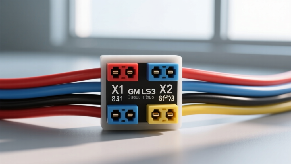
The E38 ECU utilizes two primary 80-pin connectors: X1 (Black cavity) and X2 (Gray cavity). Understanding the exact pin assignments, wire gauges, and color codes is the foundational step in any diagnostic routine. Below is a critical reference table for the most commonly tested circuits during engine management diagnostics.
| Connector | Pin | Circuit Function | Wire Color (GM OEM) | AWG / mm² | Diagnostic Specification |
|---|---|---|---|---|---|
| X1 (Black) | 1 | Ignition 1 Voltage | Pink/Black | 18 AWG (0.8) | Battery voltage in Run/Crank |
| X1 (Black) | 20 | Battery Positive (Main) | Red | 12 AWG (3.0) | Constant 12V, <0.2V drop |
| X1 (Black) | 16 | ECU Power Ground | Black/White | 12 AWG (3.0) | <0.1V drop to chassis ground |
| X1 (Black) | 73 | CAN High (HS-CAN) | Dark Blue | 18 AWG (0.8) | 2.5V Recessive / 3.5V Dominant |
| X1 (Black) | 72 | CAN Low (HS-CAN) | Dark Blue/White | 18 AWG (0.8) | 2.5V Recessive / 1.5V Dominant |
| X2 (Gray) | 1 | Injector 1 Control | Brown | 18 AWG (0.8) | PWM saturation switch, ~6 ohms |
| X2 (Gray) | 45 | Crank Sensor Signal | Dark Blue | 18 AWG (0.8) | 5V square wave, 58 pulses/rev |
| X2 (Gray) | 46 | Crank Sensor Low Ref | Black | 18 AWG (0.8) | Dedicated sensor ground |
| X2 (Gray) | 11 | TAC Motor Control 1 | Dark Blue | 16 AWG (1.5) | Bidirectional PWM, high current |
| X2 (Gray) | 12 | TAC Motor Control 2 | Dark Blue/White | 16 AWG (1.5) | Bidirectional PWM, high current |
Systematic Methodology for Troubleshooting Electrical Wiring Problems
Effective diagnosis requires moving beyond the digital multimeter's basic ohmmeter function. An ohmmeter applies a negligible load to the circuit, meaning it can show 'continuity' (near 0 ohms) even if the wire is stranded and only three copper filaments remain intact. Under the operational load of a fuel injector or a coil-on-plug (COP) ignition system, that compromised wire will suffer severe voltage drop.
Step 1: Dynamic Voltage Drop Testing on E38 Power and Ground
To accurately assess the health of the E38 power feeds, perform a dynamic voltage drop test while the circuit is under load (engine cranking or running).
- Positive Feed Test: Set your multimeter to DC Volts. Place the red probe directly on the vehicle battery positive post. Place the black probe on the E38 X1 Pin 20 (Red wire, 12 AWG) by back-probing the connector. Crank the engine. A healthy circuit will read less than 0.2V. If you read 0.5V or higher, you have high resistance in the main power feed, often caused by corrosion at the underhood fuse block or the main battery junction stud.
- Ground Circuit Test: Place the black multimeter probe on the battery negative post. Place the red probe on E38 X1 Pin 16 (Black/White wire, 12 AWG). During cranking, the voltage drop must remain below 0.1V. Exceeding 0.1V indicates a compromised ground ring terminal at the engine block or cylinder head, which is a notorious failure point on LS3 engines due to thermal cycling and oil contamination.
Step 2: Throttle Actuator Control (TAC) Motor Circuit Analysis
The LS3 electronic throttle body relies on two high-current PWM circuits (X2 Pins 11 and 12) to drive the TAC motor. Because these circuits carry significant amperage, they are highly susceptible to terminal fretting. When troubleshooting electrical wiring problems related to reduced engine power (limp mode) and DTCs like P2135 or P2119, inspect the throttle body pigtail. The 6-way Delphi Metri-Pack 280 connector is prone to terminal spread. Use a pin drag test tool to verify terminal retention; if the male blade slides into the female receptacle without a distinct 'click' and drag resistance, the pigtail must be replaced using OEM crimp tools, not solder.
High-Speed CAN Bus Diagnostics (SAE J2284 Standard)
The E38 ECU communicates with the Transmission Control Module (TCM), Body Control Module (BCM), and Electronic Brake Control Module (EBCM) via a High-Speed CAN (HS-CAN) network operating at 500 kbps. According to SAE International J2284 standards, this network requires strict physical layer integrity.
Oscilloscope Waveform Verification
A multimeter is insufficient for CAN bus validation. Connect a dual-channel automotive oscilloscope to X1 Pin 73 (CAN High) and X1 Pin 72 (CAN Low).
- Recessive State (Idle): Both CAN High and CAN Low should rest at approximately 2.5V.
- Dominant State (Active): CAN High rises to ~3.5V while CAN Low drops to ~1.5V, creating a differential voltage of 2.0V.
- Fault Symptom - Short to Ground: If CAN Low is shorted to chassis ground, the CAN High waveform will appear normal, but the network will likely crash under heavy load as the differential voltage threshold is compromised.
Termination Resistance Validation
The HS-CAN bus requires two 120-ohm terminating resistors located at opposite ends of the network (typically inside the ECU and the BCM/TCM). With the vehicle battery disconnected, measure resistance across X1 Pin 73 and Pin 72. You must read exactly 60 ohms (the parallel equivalent of two 120-ohm resistors). If you read 120 ohms, one terminating resistor or its associated wiring harness leg is open. If you read near 0 ohms, the CAN High and CAN Low wires are shorted together, often caused by chafing where the harness routes through the firewall grommet.
Common LS3 Harness Failure Modes and Repair Specifications
When executing repairs after troubleshooting electrical wiring problems, adherence to automotive-grade manufacturing standards is non-negotiable. The under-hood environment of an LS3 engine subjects wiring to extreme thermal cycling (up to 150°C near exhaust manifolds) and high-frequency vibration.
- Capillary Wicking at the Oil Pressure Sensor: The LS3 oil pressure sensor, located low on the engine block, frequently fails internally. Engine oil can bypass the sensor diaphragm and wick through the stranded 18 AWG wiring via capillary action, eventually migrating all the way up the harness and contaminating the E38 X2 connector. Always cut back the wiring until the copper strands are completely free of oil before splicing in a new pigtail.
- Prohibited Repair Methods: Never use twist-and-solder methods for under-hood sensor or injector wiring. Solder creates a rigid joint that lacks the flexibility to withstand engine vibration, leading to fatigue cracking and eventual open circuits. Furthermore, solder wicks into the wire insulation, creating a stress concentration point.
- OEM Crimp and Seal Standards: All splices must be performed using open-barrel crimp terminals applied with a calibrated ratcheting crimp tool (such as the Delphi J-38125 equivalent). Splices must be sealed using dual-wall heat shrink tubing with an inner meltable polyamide adhesive layer (e.g., DERAY® IK) to ensure a watertight, vibration-resistant seal that meets Delphi Automotive Connection Systems environmental specifications.
Conclusion
Troubleshooting electrical wiring problems in the GM LS3 E38 harness requires a disciplined, specification-driven approach. By referencing exact pinouts, utilizing dynamic voltage drop testing over simple continuity checks, and validating CAN bus differential signaling with an oscilloscope, technicians can accurately isolate faults. Adhering to strict OEM repair protocols ensures that the high-performance engine management system remains reliable under the most demanding operating conditions.