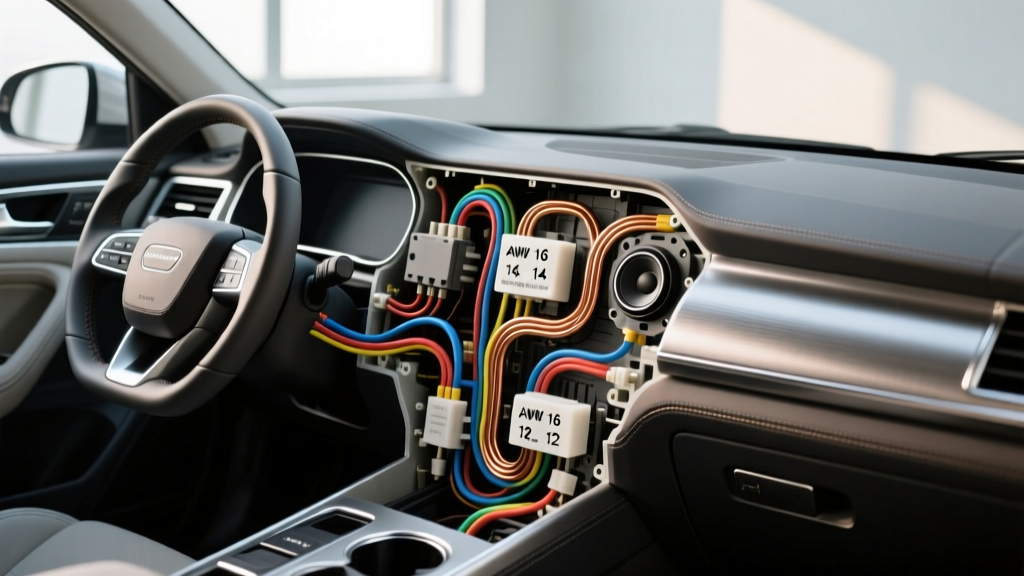
The Physics of Speaker Wire Gauges in Car Audio
When upgrading a vehicle's sound system, enthusiasts often obsess over head unit features or amplifier RMS ratings, yet completely overlook the critical role of speaker wire gauges. In a mobile 12V to 14.4V DC electrical environment, the speaker outputs from your amplifier or head unit are high-current, low-impedance AC signals. Standard car speakers typically present a 4-ohm nominal load, and subwoofers can dip to 2 ohms or even 1 ohm. According to Ohm's Law, as impedance drops, current draw increases significantly.
If the speaker wire gauges you select are too thin, the inherent resistance of the copper increases. This results in two major issues: I²R power loss (where electrical energy is wasted as heat rather than acoustic output) and a degraded damping factor. The damping factor is the amplifier's ability to act as an electromagnetic brake on the speaker cone. When wire resistance is too high, the amplifier loses control over the voice coil, resulting in boomy, uncontrolled mid-bass and poor transient response. For automotive audio, where door panels are acoustically hostile environments, maintaining a high damping factor through proper wire sizing is non-negotiable.
AWG Specification Chart for Automotive Speakers
The American Wire Gauge (AWG) system dictates the physical diameter and current-carrying capacity of the wire. Below is the definitive reference chart for selecting the correct speaker wire gauges based on your amplifier's output and the speaker's impedance. These calculations assume a standard 10-foot run from the amplifier to the speaker, which is typical for most sedan and truck installations.
| AWG Size | Max Wattage (4-Ohm) | Max Wattage (2-Ohm) | Resistance per 10ft | Recommended Automotive Application |
|---|---|---|---|---|
| 18 AWG | 50W RMS | 25W RMS | 0.064 Ohms | Stock head units, low-power dash tweeters, basic factory upgrades |
| 16 AWG | 100W RMS | 50W RMS | 0.040 Ohms | Standard 6.5-inch coaxial and component door speakers |
| 14 AWG | 200W RMS | 100W RMS | 0.025 Ohms | High-power mid-bass drivers, 8-inch midrange, dedicated amp runs |
| 12 AWG | 400W RMS | 200W RMS | 0.016 Ohms | Passive subwoofers, high-SPL competition builds, long-distance runs |
Material Matters: OFC vs. CCA
Before purchasing, you must understand the metallurgy of your wire. The market is flooded with Copper-Clad Aluminum (CCA) wire, which is significantly cheaper than Oxygen-Free Copper (OFC). CCA wire features an aluminum core coated with a microscopic layer of copper. Because aluminum has roughly 61% of the conductivity of copper, a 14 AWG CCA wire performs electrically like a 16 AWG or even 18 AWG OFC wire.
More importantly, car doors are wet environments. If moisture breaches the wire jacket, the exposed aluminum core undergoes rapid galvanic corrosion, turning into a white, non-conductive powder. This causes open circuits and intermittent speaker dropouts. Always strip a small section of the wire at the store; if the cross-section is silver or white, it is CCA. For premium car audio installations, strictly specify 100% OFC wire to ensure longevity and optimal conductivity.
Step-by-Step Routing and Installation Guide
Selecting the right speaker wire gauges is only half the battle. Proper routing ensures the wire survives the harsh environment of a vehicle chassis.
Step 1: Interior Teardown and Harness Identification
Begin by removing the door panels, kick panels, and B-pillar trims using a plastic trim removal tool to avoid snapping fragile retention clips. If you are retaining the factory amplifier and only upgrading the speakers, you must locate the high-level speaker outputs. Set your digital multimeter (DMM) to AC Voltage. With the stereo playing a 50Hz test tone, probe the factory harness wires. The wires that show a fluctuating AC voltage (typically 2V to 8V depending on volume) are your speaker outputs. Label them immediately.
Step 2: Navigating the Door Jamb Grommet
Routing wire from the cabin into the door is the most challenging part of the installation. The rubber door boot contains factory wiring, side-impact airbag cables, and window track mechanisms. Never blindly push wire through this grommet. Instead, use a stiff piece of wire (like a straightened metal coat hanger) or a dedicated fiberglass fish tape. Lubricate the tip of the fish tape with a light silicone spray to help it glide through the tight rubber passages. Tape your new speaker wire securely to the fish tape using electrical tape, creating a smooth, tapered head to prevent snagging on internal rubber flaps.
Step 3: Securing and Looming the Wire
Once inside the door cavity, the wire is exposed to rain runoff, sharp stamped metal edges, and the window glass track. Bare wire will eventually chafe against the metal door skin, causing a short circuit that triggers your amplifier's protection mode. Wrap the entire length of the speaker wire in Tesa cloth tape (fleece tape) or corrugated split-loom tubing. This prevents rattles against the door card and protects against moisture. Secure the loomed wire to existing factory harnesses using UV-resistant zip ties, ensuring you route the wire well above the window glass's downward travel path.
Termination and Polarity Standards
Proper termination prevents stray copper strands from shorting against the door chassis. It also ensures consistent acoustic phasing across all four corners of the vehicle.
EIA/CTA Color Code Standards
The Consumer Technology Association (CTA) establishes standard color codes for mobile electronics to ensure uniformity. When wiring your amplifier or head unit, adhere strictly to these conventions:
- Left Front: White (Positive +) / White with Black Stripe (Negative -)
- Right Front: Gray (Positive +) / Gray with Black Stripe (Negative -)
- Left Rear: Green (Positive +) / Green with Black Stripe (Negative -)
- Right Rear: Purple (Positive +) / Purple with Black Stripe (Negative -)
Connector Selection and Crimping
For standard 6.5-inch door speakers, use 16-14 AWG female quick-disconnect spade terminals. While soldering is popular in home audio, the constant vibration and shock of car doors slamming can cause rigid solder joints to fatigue and crack over time. The Mobile Electronics Certification Program (MECP) recommends high-quality mechanical crimps for mobile environments. Use a proper ratcheting crimp tool to ensure a gas-tight connection, then seal the terminal with dual-wall adhesive heat shrink tubing. The adhesive lining melts and seals out moisture, preventing the copper from oxidizing.
Troubleshooting Common Installation Failures
Even with the correct speaker wire gauges, installation errors can degrade system performance. Use this diagnostic tree to resolve common issues:
- Symptom: Muffled bass, poor soundstage imaging, and lack of punch.
Cause: Out-of-phase wiring. One or more speakers have reversed polarity, causing acoustic cancellation.
Fix: Verify the solid/stripe color convention at both the amp and the speaker. Use a 9V battery to briefly touch the speaker terminals; if the cone moves inward instead of outward, reverse the polarity at the amplifier. - Symptom: High-frequency roll-off or a muddy, lifeless sound.
Cause: Wire gauge too small for the run length, or excessive CCA wire used, causing high-frequency AC signals to degrade due to the skin effect and high resistance.
Fix: Upgrade to 14 AWG OFC wire, especially for component tweeters and midranges. - Symptom: Amplifier goes into protect mode specifically when rolling down the windows.
Cause: Speaker wire pinched between the window track and the door frame, shorting the negative or positive terminal to the grounded door chassis.
Fix: Remove the door panel, re-route the wire away from the window mechanism, and apply heavy split-loom protection. - Symptom: Intermittent speaker dropout over bumps.
Cause: Loose quick-disconnect spades or a broken CCA wire core inside the insulation.
Fix: Squeeze the female spade connectors slightly with pliers for a tighter grip on the speaker tab, or replace the wire run if internal fracture is suspected.
Authoritative References and Standards
For further reading on automotive electrical standards and wire specifications, consult the following industry resources:
- SAE J1128 Standard - Society of Automotive Engineers guidelines for low-tension primary cable and wire insulation requirements in automotive applications.
- MECP Certification Study Guides - Mobile Electronics Certification Program best practices for wire routing, termination, and safety in vehicle modifications.
- Consumer Technology Association (CTA) - Industry standards for mobile electronics color-coding, impedance matching, and amplifier testing protocols.
By respecting the physics of electrical current and adhering to proper routing techniques, your chosen speaker wire gauges will deliver clean, uncolored audio to your drivers for the lifespan of the vehicle.