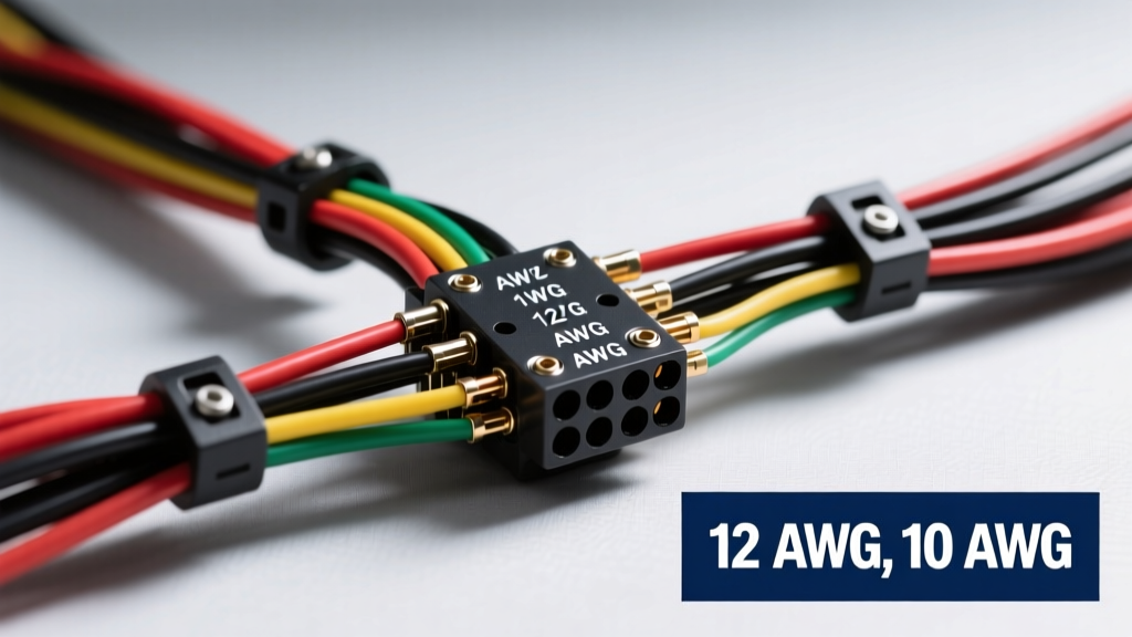
The Physics of Low-Frequency Current Draw
When designing a mobile audio electrical system, selecting the correct sub speaker wire gauge is arguably more critical than wiring mid-range drivers or tweeters. Subwoofers operate at the lowest end of the audible frequency spectrum (typically 20Hz to 120Hz) and require massive amounts of continuous current to physically move heavy cone assemblies and large voice coils. Unlike high-frequency signals, which are highly susceptible to the skin effect and capacitance, low-frequency subwoofer signals are governed almost entirely by DC resistance and raw current-carrying capacity. If the wire gauge is undersized, the resistance of the conductor increases, leading to severe voltage drop, thermal runaway, and a catastrophic loss of electromechanical control over the driver.
To accurately size your wiring, you must move beyond marketing wattage and focus on continuous RMS current draw. The fundamental formula for calculating the maximum current flowing through a speaker wire is derived from Joule's first law: I = √(P / R), where I is current in Amperes, P is RMS wattage, and R is the nominal impedance of the voice coil in Ohms (Ω). For example, an amplifier outputting 1,000 Watts RMS into a 2Ω load will generate approximately 22.36 Amps of continuous current. This current level dictates the minimum cross-sectional area of the copper required to prevent the wire from becoming a bottleneck or a fire hazard.
Sub Speaker Wire Gauge Specification Matrix
The following technical matrix outlines the maximum continuous RMS wattage thresholds for standard Oxygen-Free Copper (OFC) conductors. These specifications assume a standard 15-foot run from the amplifier to the subwoofer enclosure, which is typical for sedan and SUV trunk-mounted installations. If your run exceeds 20 feet, you must step up one AWG size to compensate for the accumulated resistance over the extended distance.
| AWG Size | Max Current (Amps) | Max RMS @ 4Ω | Max RMS @ 2Ω | Max RMS @ 1Ω | Strand Count (Fine) |
|---|---|---|---|---|---|
| 18 AWG | 7.0A | 200W | 100W | 50W | 16 |
| 16 AWG | 10.0A | 400W | 200W | 100W | 26 |
| 14 AWG | 15.0A | 900W | 450W | 225W | 41 |
| 12 AWG | 20.0A | 1600W | 800W | 400W | 65 |
| 10 AWG | 30.0A | 3600W | 1800W | 900W | 105 |
| 8 AWG | 45.0A | 8100W | 4050W | 2025W | 168 |
Note: The strand counts listed represent standard fine-stranding configurations used in high-flexibility automotive audio cables. Coarse-stranding reduces flexibility and is not recommended for routing through tight vehicle bulkheads or door hinges.
Conductor Metallurgy: OFC vs. CCA
A critical variable in sub speaker wire gauge selection is the base metallurgy of the conductor. The market is flooded with Copper-Clad Aluminum (CCA) wire, which is significantly cheaper to manufacture but possesses vastly inferior electrical characteristics compared to pure Oxygen-Free Copper (OFC). According to ePanorama wire resistance tables, aluminum has a resistivity approximately 1.6 times higher than copper. Because CCA wire relies on a thin copper plating over an aluminum core, its overall resistance closely mirrors that of aluminum at low frequencies.
If you are forced to use CCA wire due to budget constraints or availability, you must apply a strict derating factor to the specification matrix above. To achieve the same current-carrying capacity and voltage drop characteristics as OFC, you must increase the CCA wire diameter by at least one, and preferably two, AWG sizes. For instance, if your system requires 12 AWG OFC for an 800W RMS @ 2Ω load, you must utilize 10 AWG or 8 AWG CCA wire to prevent thermal degradation and signal loss. For high-fidelity and high-SPL (Sound Pressure Level) competition vehicles, OFC is the only acceptable standard.
Damping Factor and Electromechanical Control
Beyond thermal limits, the sub speaker wire gauge directly impacts the system's Damping Factor (DF). Damping factor is the amplifier's ability to control the physical movement of the subwoofer cone, particularly during transient stops and direction reversals. The formula for system damping factor is DF = Z_load / (R_source + R_wire), where Z_load is the speaker impedance, R_source is the amplifier's internal output impedance, and R_wire is the total resistance of the speaker wire run.
Modern Class D amplifiers feature incredibly low internal output impedance (often below 0.01Ω). However, if you use an undersized 16 AWG wire for a high-current subwoofer, the wire resistance might add 0.05Ω to the circuit. This seemingly small addition drastically reduces the damping factor, resulting in 'boomy', loose, and uncontrolled bass response. The amplifier loses its electromagnetic braking capability, and the voice coil continues to oscillate after the audio signal has stopped. To maintain a tight, accurate transient response in a 2Ω subwoofer configuration, maintaining a wire resistance of less than 0.01Ω per foot is mandatory, which typically necessitates 12 AWG or 10 AWG OFC wire for runs over 10 feet.
Environmental Routing and SAE Standards
Automotive environments subject wiring to extreme temperature fluctuations, vibration, and chemical exposure. When routing sub speaker wires, adherence to SAE J1128 standards for Low Tension Primary Cable is highly recommended for the jacket material. Standard PVC jackets can become brittle and crack when exposed to the high ambient temperatures found near exhaust tunnels or under-hood firewall pass-throughs.
If your wiring must pass through the engine bay or near heat sources, you must utilize wire with a cross-linked polyethylene (XLPE) or Teflon jacket rated for 125°C to 150°C. Furthermore, any wire passing through metal bulkheads or firewalls must be protected by a rubber grommet and secured with split-loom tubing to prevent chafing. A short circuit on a high-current 8 AWG subwoofer wire can instantly ignite surrounding insulation and vehicle carpeting, as the amplifier's 40A+ output rail will bypass standard factory fusing if the short occurs between the amplifier and the speaker.
Termination Protocols and Cold Creep
The physical termination of the sub speaker wire is a frequent point of failure in high-current mobile audio systems. Most high-power amplifiers and subwoofer binding posts utilize set-screw terminals. When bare copper wire is compressed directly under a set screw, it is subject to a metallurgical phenomenon known as 'cold creep' or 'stress relaxation'. Over time, the copper deforms under the constant mechanical pressure of the screw, causing the connection to loosen. This loose connection increases contact resistance, generating localized heat that can melt the amplifier's terminal block.
To prevent cold creep, professional installers utilize ferrule crimps or properly tinned wire ends. If tinning the wire with rosin-core solder, it is vital to ensure the set screw is retightened after 48 hours of use, as the solder itself is softer than copper and will also compress over time. Alternatively, using high-quality spade terminals or ring terminals crimped with a ratcheting tool provides the most reliable, vibration-resistant connection, ensuring consistent contact pressure and optimal current transfer.
Troubleshooting Decision Tree: Voltage Drop and Thermal Issues
When diagnosing subwoofer performance issues or physical wire anomalies, follow this systematic decision tree to identify gauge-related faults:
- Symptom: Subwoofer output drops significantly during heavy bass transients, and amplifier clipping indicators illuminate prematurely.
Cause: Severe voltage drop due to undersized wire gauge or excessive run length.
Fix: Measure AC voltage at the amplifier speaker terminals versus the subwoofer binding posts under load. If the delta exceeds 5%, upgrade to the next largest AWG size. - Symptom: Wire jacket feels warm to the touch after 15 minutes of continuous play at high volume.
Cause: Thermal saturation; the wire is operating near or above its continuous amperage rating.
Fix: Immediately reduce volume. Replace CCA wire with OFC, or step up two AWG sizes to increase the thermal mass and surface area for heat dissipation. - Symptom: Bass sounds 'loose' or lacks impact, despite proper amplifier tuning and enclosure volume.
Cause: Damping factor degradation caused by high wire resistance.
Fix: Verify wire material (ensure it is not CCA). Replace thin-gauge wire with 12 AWG or 10 AWG OFC to minimize series resistance and restore amplifier braking control.
For further technical validation on mobile audio power ratings and testing methodologies, refer to the Consumer Technology Association (CTA) standards directory, specifically CTA-2015, which governs mobile audio power amplifier power rating and ensures that the RMS figures used to calculate your wire gauge are based on verified, continuous testing protocols rather than inflated peak marketing metrics.