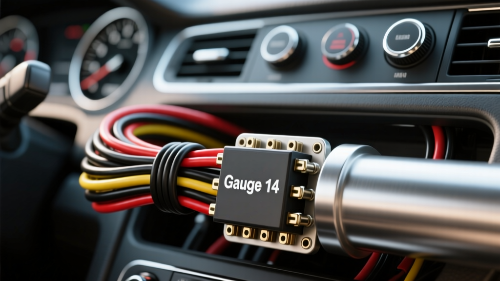
Introduction: The 14 AWG Bottleneck in Car Audio
When upgrading a vehicle's sound system, selecting the correct conductor size is critical for preserving audio fidelity and amplifier stability. Many enthusiasts assume speaker wire gauge 14 is universally adequate for all non-subwoofer applications. While 14 AWG Oxygen-Free Copper (OFC) is an excellent choice for 50W to 100W RMS component sets, pushing it beyond its physical limitations leads to thermal compression, altered damping factors, and audible distortion. This step-by-step troubleshooting flow will help you diagnose whether your current wiring is the root cause of your audio anomalies, utilizing precise electrical measurements and industry-standard diagnostic procedures.
Step 1: Symptom Isolation and the Decision Matrix
Before grabbing a multimeter, you must categorize the distortion. Audio degradation caused by inadequate wire gauge manifests differently than a blown voice coil or a clipping amplifier. Use the following symptom-cause-fix matrix to determine if your wiring is the primary suspect.
| Symptom | Electrical Behavior | Is 14 AWG the Culprit? | Corrective Action |
|---|---|---|---|
| Muddy, uncontrolled mid-bass | High wire resistance ruins amplifier damping factor | Yes, if run exceeds 15 feet or wire is CCA | Upgrade to 12 AWG OFC or shorten run |
| Tweeter harshness at high volume | High-frequency skin effect and inductive reactance | Rarely; usually a crossover or EQ issue | Check passive crossover capacitors |
| Amp thermal shutdown during heavy bass | Impedance drop causing excessive current draw | No; 14 AWG handles chassis current fine | Check for shorted voice coils or pinched wires |
| Volume drops after 10 minutes of play | Thermal compression in undersized CCA wire | Yes, if using Copper-Clad Aluminum (CCA) | Replace entirely with 14 AWG OFC |
Step 2: Verify Wire Composition (The CCA Trap)
The most common reason a 14 AWG speaker wire fails to perform is that it isn't actually 14 AWG copper. The market is flooded with Copper-Clad Aluminum (CCA) wire. According to the SAE J1128 Low Tension Primary Cable Standard, automotive copper wiring must meet strict conductivity benchmarks. CCA wire only has a thin copper coating over an aluminum core. Because aluminum has roughly 61% of the conductivity of copper, a 14 AWG CCA wire performs electrically like a 16 AWG or even 18 AWG OFC wire.
The Scratch and Burn Test
- Visual Inspection: Strip back 1/2 inch of the wire insulation. Use a sharp utility knife to scrape the side of a single copper strand.
- Color Check: If the metal underneath the copper color is silvery-white, you have CCA wire. True OFC will remain a consistent copper/bronze color all the way through.
- The Burn Test: Hold a lighter to the stripped strands. CCA wire will quickly melt and droop, turning to white ash. True OFC will glow red hot but maintain its structural integrity and turn black with soot.
If your wire fails this test, your troubleshooting stops here. Replace the run with certified 14 AWG OFC before proceeding. For more on wire composition, refer to the Basic Car Audio Electronics (BCAE1) Speaker Wire Guide.
Step 3: Calculate Voltage Drop and Damping Factor
If you have confirmed your wire is true 14 AWG OFC, the next step is to measure its impact on the amplifier's damping factor. Damping factor is the amplifier's ability to control the speaker cone's movement, particularly after a bass transient. It is calculated by dividing the speaker's nominal impedance by the total output impedance (which includes the wire's resistance).
The 14 AWG Resistance Math
True 14 AWG OFC has a resistance of approximately 2.525 milliohms per foot. In a car audio application, you must calculate the round-trip distance (positive and negative leads).
- Run Length: 12 feet from amp to door speaker.
- Round Trip: 24 feet total.
- Total Wire Resistance: 24 ft × 0.002525 Ω/ft = 0.0606 Ω.
- Speaker Impedance: 4 Ω nominal.
- Total Circuit Resistance: 4.0606 Ω.
While 0.06 ohms seems negligible, if you are running a 2-ohm stable component set or wiring multiple speakers in parallel, this resistance increases proportionally, severely degrading the damping factor. If your mid-bass sounds 'loose' or 'ringy', measure the exact run length. If the round-trip exceeds 20 feet for a 2-ohm load, 14 AWG is insufficient, and you must step up to 12 AWG.
Step 4: Inspecting Terminations and the Step-Down Bottleneck
A massive, often overlooked failure point in car audio is the physical termination of the wire. Most aftermarket 6.5-inch coaxial and component speakers utilize standard 0.187-inch (4.7mm) spade terminals for the positive input and 0.110-inch (2.8mm) spades for the negative.
Herein lies the problem: standard 0.187-inch crimp terminals are designed for 18 to 22 AWG wire. Forcing 14 AWG wire into these tiny crimp barrels results in crushed strands, incomplete mechanical connections, and high-resistance choke points.
Proper Termination Procedure for 14 AWG
- Strip the Wire: Remove exactly 5/16 inch of insulation from the 14 AWG wire.
- Use Step-Down Connectors: Utilize nylon-insulated step-down butt connectors (rated 16-14 AWG to 22-18 AWG) to transition from the thick 14 AWG main run to a short 6-inch pigtail of 18 AWG wire.
- Crimp and Solder: Crimp the 14 AWG side with the blue die on your crimping tool. Crimp the 18 AWG side with the red die. For maximum conductivity, flow rosin-core solder into the barrel.
- Attach Spades: Crimp standard 18 AWG female quick-slide disconnects onto the 18 AWG pigtail, ensuring a snug fit on the speaker's spade terminals.
- Seal: Apply adhesive-lined marine heat shrink over all connections to prevent corrosion from door panel moisture.
Step 5: Verify Standard EIA Color Codes and Routing
When troubleshooting a system where the installer used 14 AWG wire but failed to label the runs, you must trace the wires back to the amplifier or DSP. To maintain signal phase coherence, adhere strictly to the Electronic Industries Alliance (EIA) standard color codes for automotive speaker wiring:
- Front Left: White (Positive) / White with Black Stripe (Negative)
- Front Right: Gray (Positive) / Gray with Black Stripe (Negative)
- Rear Left: Green (Positive) / Green with Black Stripe (Negative)
- Rear Right: Purple (Positive) / Purple with Black Stripe (Negative)
Routing Warning: Never run 14 AWG speaker wires parallel to RCA signal cables or 12V power cables. While speaker-level signals are high-voltage and less susceptible to alternator whine than RCA cables, running them alongside high-current power wires can induce electromagnetic interference (EMI) into the amplifier's feedback loop. Always route speaker wires down the opposite side of the vehicle's transmission tunnel from the main power wire.
Step 6: Multimeter Load Testing
The final step in the troubleshooting flow is verifying the integrity of the completed 14 AWG run under load.
- Disconnect the speaker wire from the amplifier.
- Set your digital multimeter (DMM) to the lowest DC Ohms setting (usually 200Ω).
- Short the positive and negative wires together at the speaker end using a heavy-gauge jumper wire.
- Measure the resistance at the amplifier end.
- Your DMM should read between 0.05Ω and 0.12Ω (depending on run length and your DMM's internal lead resistance). If the reading fluctuates or reads OL (Open Loop), you have a broken strand or a failed crimp inside the door boot.
Summary: When to Keep It and When to Upgrade
Speaker wire gauge 14 remains the gold standard for standard 4-ohm, 50-100W RMS door speakers, provided it is true OFC and properly terminated. However, if you are driving 2-ohm loads, running wires to a trunk-mounted subwoofer, or pushing high-excursion mid-bass drivers with 150W+ RMS, the physical limitations of 14 AWG will introduce resistance that degrades your damping factor and audio quality. By following this systematic troubleshooting flow, you can confidently isolate wiring faults, eliminate distortion, and ensure your automotive electrical system delivers pristine, uncolored sound.
For further reference on amplifier matching and wire sizing, consult the Crutchfield Car Audio Wire Gauge Guide to cross-reference your specific amplifier's RMS output against your vehicle's physical wire run lengths.