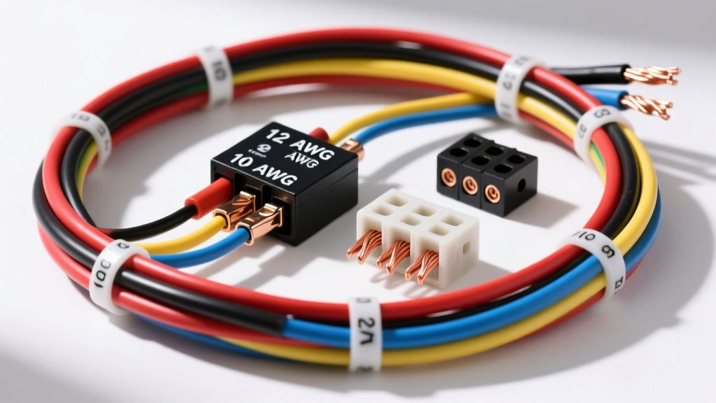
The Core Question: Which Wire Gauge for 20 Amps?
When wiring high-draw automotive accessories like electric fuel pumps, heavy-duty cooling fans, or winch controllers, selecting the correct wire gauge for 20 amps is critical. A common misconception is that 12 AWG wire is sufficient for a 20-amp circuit because standard chassis wiring charts often list its maximum ampacity at 25 amps. However, in automotive 12-volt systems, maximum ampacity is only half the equation; voltage drop is the hidden killer of high-draw components.
According to SAE J1128 standards for low-tension primary cable, a 12 AWG wire will suffer significant voltage loss over the long routing distances typical in vehicle chassis. If an electric fuel pump receives 11.5 volts instead of 13.8 volts due to undersized wiring, it will draw more current to compensate, run hotter, and ultimately fail prematurely. For a robust, professional-grade 20-amp circuit, 10 AWG GXL (Cross-Linked Polyethylene) wire is the minimum recommended standard for runs exceeding 6 feet.
Voltage Drop: The Hidden Killer of 20-Amp Circuits
To understand why we specify 10 AWG over 12 AWG for a 20-amp load, we must calculate the voltage drop. The formula is: Voltage Drop = Current x (2 x One-Way Distance) x Resistance per Foot.
Below is a technical specification chart comparing 12 AWG and 10 AWG GXL wire on a standard 13.8V charging system with a 20-amp constant draw:
| Wire Gauge (AWG) | One-Way Run | Total Loop Length | Resistance (Loop) | Voltage Drop (@ 20A) | Percentage Drop | Verdict |
|---|---|---|---|---|---|---|
| 12 AWG GXL | 5 ft | 10 ft | 0.0161 Ω | 0.32 V | 2.3% | Acceptable |
| 12 AWG GXL | 10 ft | 20 ft | 0.0323 Ω | 0.64 V | 4.6% | Unacceptable (>3%) |
| 10 AWG GXL | 10 ft | 20 ft | 0.0203 Ω | 0.40 V | 2.9% | Acceptable |
| 10 AWG GXL | 15 ft | 30 ft | 0.0305 Ω | 0.61 V | 4.4% | Unacceptable (Step up to 8 AWG) |
Note: The Society of Automotive Engineers (SAE) recommends keeping voltage drop below 3% (0.41V) for critical powertrain electronics and high-draw motors.
Tools and Materials for a Professional Installation
Do not use THHN building wire from a hardware store; its insulation is not rated for automotive under-hood temperatures or fluid exposure. Gather the following OEM-grade materials:
- Primary Wire: 10 AWG GXL (Red for power, Black for ground).
- Control Wire: 16 AWG GXL (Blue for switched 12V+, Black for ground).
- Relay: Standard ISO Mini Relay (Bosch-style, 40A rating, 5-pin with 87a omitted or 4-pin).
- Overcurrent Protection: 25A ATC/ATO Blade Fuse with an inline waterproof holder, or a 30A Maxi fuse for the main battery feed.
- Terminals: Adhesive-lined (dual-wall) heat-shrink ring terminals and Metri-Pack 280 sealed female terminals.
- Tools: Ratcheting wire crimper (specifically for non-insulated terminals), wire strippers, and a heat gun.
Step-by-Step Wiring Guide: 20-Amp Electric Fuel Pump
This guide assumes you are installing a high-pressure EFI fuel pump drawing 18-20 amps, controlled by an ECU or ignition switch via a relay.
Step 1: Route the Primary Power Feed (Pin 30)
Measure the distance from the battery positive terminal to the relay mounting location, and add 2 feet for service loops. Cut your 10 AWG Red GXL wire. Crimp a 10 AWG ring terminal on one end and secure it to the battery positive. Crucial: Install the 25A inline fuse holder within 6 inches of the battery terminal to protect the entire cable run. Route the wire to the relay and terminate with a Metri-Pack 280 female terminal, inserting it into Pin 30 of the relay socket.
Step 2: Wire the Load Circuit (Pin 87)
Cut another length of 10 AWG Red GXL. Terminate one end into Pin 87 of the relay socket. Route this wire through the firewall or under the chassis to the fuel pump. At the pump, use a sealed, weather-pack connector to mate with the pump harness. The ground wire from the pump must be 10 AWG Black GXL, grounded directly to the chassis using a self-tapping star washer within 12 inches of the pump to minimize the ground loop.
Step 3: Wire the Control Circuit (Pins 85 & 86)
The control circuit requires minimal current (approx. 0.15A), so 16 AWG wire is perfectly adequate.
- Pin 86 (Coil Power): Connect 16 AWG Blue wire to a switched 12V+ source (e.g., ECU fuel pump trigger or ignition-on fuse panel).
- Pin 85 (Coil Ground): Connect 16 AWG Black wire to a clean, bare-metal chassis ground.
When the ECU sends the 12V+ signal to Pin 86, the electromagnetic coil energizes, pulling the internal switch closed and allowing the heavy 10 AWG current to flow from Pin 30 to Pin 87.
Standard ISO Relay Pinout and Color Code Chart
Reference this chart when wiring your Bosch-style relay harness to ensure correct polarity and circuit separation. For more on relay architectures, consult Delphi Automotive Connection Systems documentation.
| Pin Number | Function | Recommended Wire Gauge | Standard Color Code |
|---|---|---|---|
| 30 | Common / Main Power In | 10 AWG (or 8 AWG for long runs) | Red (Fused 12V+) |
| 87 | Normally Open / Power Out | 10 AWG (or 8 AWG for long runs) | Red (To Load) |
| 86 | Coil Power In (Trigger) | 16 AWG | Blue or White (Switched 12V+) |
| 85 | Coil Ground | 16 AWG | Black (Chassis Ground) |
Crimping and Termination Best Practices
The most common cause of failure in 20-amp circuits is not the wire size, but poor termination. A loose crimp creates high resistance, generating heat that melts the relay socket. 1. Strip the wire precisely: Do not nick the copper strands. 2. Use adhesive-lined heat shrink: When crimping ring terminals, use dual-wall heat shrink. The inner layer of adhesive melts and seals the copper strands from oxygen and moisture, preventing green corrosion and voltage drop over time. 3. Pull-test: After crimping, give the wire a firm tug. A properly executed ratcheting crimp will withstand over 40 lbs of pull force without slipping.
Troubleshooting Common 20-Amp Circuit Failures
Even with the correct wire gauge for 20 amps, installation errors can cause symptoms. Use this diagnostic tree:
Symptom 1: Relay Clicks, But Fuel Pump Doesn't Run
- Cause: High resistance on the high-current side (Pins 30/87) or a poor pump ground.
- Fix: Use a multimeter to measure voltage directly at the pump terminals while the relay is engaged. If you read 11V or lower at the pump but 13.8V at the battery, you have a voltage drop. Check for a loose crimp at Pin 87 or a corroded chassis ground.
Symptom 2: Relay Socket Gets Hot and Melts
- Cause: Micro-arcing inside the socket due to loose female Metri-Pack terminals, or the circuit is drawing sustained amperage above the 20A design (e.g., a failing motor drawing 35A).
- Fix: Check the amp draw with an inductive clamp meter. If the draw is normal (18-20A), replace the relay socket and ensure the female terminals have high retention force. Never bend the male relay tabs to 'tighten' the fit.
Symptom 3: Intermittent Operation When Engine is Hot
- Cause: Using PVC-insulated wire instead of GXL/TXL, causing the insulation to soften and short against the chassis, or thermal expansion breaking a poor solder joint.
- Fix: Inspect the wiring harness near exhaust manifolds. Replace any non-automotive wire with GXL and cover the harness in split-loom corrugated tubing with Tesa tape for abrasion resistance.
For comprehensive wiring diagrams and pre-terminated harness solutions, resources like Painless Performance Products offer excellent reference materials for custom EFI and relay installations. Always verify your specific component's amperage draw before finalizing your wire gauge selection.