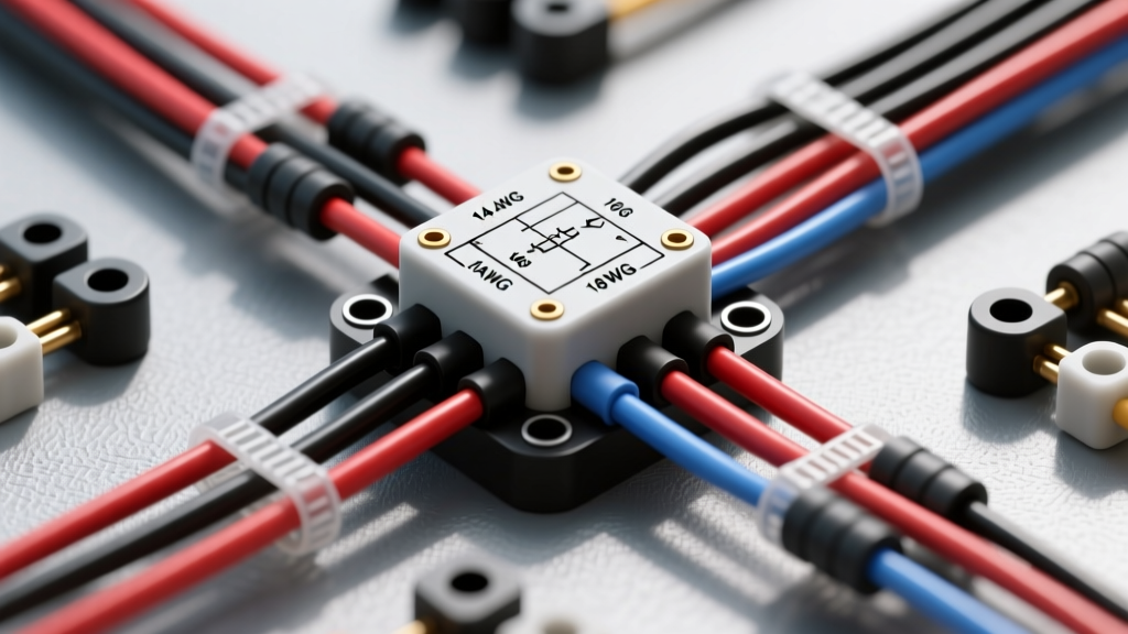
The Anatomy of an Automotive Lighting Circuit
When upgrading auxiliary lamps, off-road LED bars, or high-output halogen headlights, guessing the correct wire gauge for lights is a critical error that leads to severe voltage drop, dim illumination, and potentially catastrophic harness fires. Automotive lighting circuits demand precise wire sizing based on the total amperage draw and the physical length of the wire run. Unlike low-draw sensor circuits, lighting harnesses carry continuous, high-current loads that generate significant thermal energy.
To manage these loads safely, modern automotive electrical systems utilize a relay-switched architecture. This separates the high-current power delivery from the low-current trigger switch, allowing you to use heavy-duty cables for the lights themselves while preserving the delicate OEM dashboard switchgear. In this complete wiring diagram walkthrough, we will dissect a standard 4-pin automotive relay harness, detailing the exact AWG requirements, SAE wire specifications, and terminal configurations for every node in the circuit.
Complete Wiring Diagram Walkthrough: 4-Pin Relay Harness
A standard ISO mini relay (Bosch-style) features five pins, though only four are typically used for basic lighting applications. Understanding the current flow through pins 30, 87, 85, and 86 is essential for selecting the proper wire gauge for lights and preventing bottleneck restrictions in your harness.
Pin 30: Battery Power Feed (High Current Source)
Pin 30 is the main power input directly from the vehicle’s battery positive terminal. This wire must be sized to handle the maximum continuous amperage of the connected lights, plus a 20% safety margin. For a standard 52-inch LED light bar drawing 24 amps, or a pair of 100W halogen driving lights drawing 16 amps, 12 AWG GXL wire is the minimum requirement. If the run from the battery to the relay exceeds 10 feet, or if the load exceeds 25 amps, you must step up to 10 AWG to mitigate voltage drop. This wire should always be protected by an inline Maxi or ANL fuse rated 125% of the load, placed within 6 inches of the battery terminal.
Pin 87: Load Output to Lights (High Current Delivery)
Pin 87 is the normally open (NO) contact that delivers power to the lights when the relay coil is energized. The wire gauge for Pin 87 must exactly match the gauge used on Pin 30. If you use 12 AWG on the battery side but step down to 16 AWG on the load side to make routing through the firewall or grille easier, you have created a dangerous bottleneck. The 16 AWG wire will act as a resistor, generating excessive heat and melting the insulation. Always maintain consistent AWG sizing across the entire high-current path (Pins 30 and 87).
Pins 85 & 86: The Trigger Circuit (Low Current Control)
Pins 85 and 86 control the internal electromagnetic coil of the relay. This circuit draws very little current—typically between 0.15A and 0.30A depending on the relay’s coil resistance (usually 70 to 120 ohms). Because the amperage is negligible, 16 AWG or 18 AWG TXL wire is perfectly adequate for the trigger circuit.
- Pin 86 (Switch Input): Connects to your dashboard switch, OEM headlight signal wire, or an ignition-switched 12V source.
- Pin 85 (Ground): Must be grounded to a clean, bare-metal chassis point. Do not rely on painted surfaces or plastic splash shields for this ground.
Wire Gauge for Lights: Application Specification Chart
Selecting the right wire gauge for lights requires calculating the total wattage and converting it to amperage using Ohm’s Law (Amps = Watts ÷ Volts). Assuming a running vehicle voltage of 13.8V, use the reference chart below to determine your baseline AWG requirements before factoring in wire length.
| Lighting Application | Total Wattage | Current Draw (Amps @ 13.8V) | Minimum Wire Gauge (Under 10 ft) | Minimum Wire Gauge (10-20 ft) |
|---|---|---|---|---|
| LED Rock Lights (Pod of 8) | 36W | 2.6A | 18 AWG | 16 AWG |
| OEM H11 Halogen Headlights (Pair) | 110W | 7.9A | 14 AWG | 12 AWG |
| Aftermarket LED Headlights (Pair) | 80W | 5.8A | 16 AWG | 14 AWG |
| 30-Inch LED Light Bar | 180W | 13.0A | 12 AWG | 10 AWG |
| 52-Inch LED Light Bar | 288W | 20.8A | 10 AWG | 8 AWG |
Calculating Voltage Drop in Lighting Harnesses
According to the Blue Sea Systems Circuit Calculator, voltage drop is the silent killer of automotive lighting performance. A halogen bulb receiving 11.5V instead of 13.8V will lose nearly 30% of its luminous output and shift to a yellow, inefficient color temperature. To calculate voltage drop, you must account for the total round-trip length of the circuit (from the battery, to the relay, to the light, and back to the ground).
The formula for DC voltage drop is: VD = (2 x L x I x R) / 1000, where L is the one-way length in feet, I is current in amps, and R is the wire resistance per 1,000 feet. For example, running a 20A LED light bar with 15 feet of 12 AWG wire (Resistance = 1.588 ohms/1000ft) results in a voltage drop of 0.95V. While acceptable, stepping up to 10 AWG reduces that drop to 0.60V, ensuring maximum lumen output. For critical lighting applications, the Painless Performance wire sizing guidelines recommend keeping voltage drop below 3% (0.41V on a 13.8V system).
Wire Insulation and Terminal Specifications
Choosing the correct wire gauge for lights is only half the battle; the insulation type and termination method dictate the long-term reliability of the harness. Standard PVC (polyvinyl chloride) wire found in hardware stores is entirely unsuitable for under-hood automotive applications. It becomes brittle at high temperatures and melts near exhaust headers.
Always specify SAE J1128 compliant GXL or TXL wire. As detailed in the SAE J1128 Low-Tension Primary Cable standard, GXL (General Cross-Linked) features a thin-wall, cross-linked polyethylene insulation that withstands continuous temperatures up to 125°C (257°F) and resists automotive fluids like oil, coolant, and battery acid. TXL offers even thinner insulation for tight spaces while maintaining the same thermal properties.
For terminations, abandon generic butt-splices. Use Delphi Weather-Pack or Metri-Pack 280 sealed connectors for the light fixtures to prevent moisture intrusion and galvanic corrosion. At the relay socket, use heavy-duty brass female spade terminals with an integrated locking tang to prevent vibration-induced disconnects, and always seal the crimps with adhesive-lined, dual-wall heat shrink tubing.
Expert Troubleshooting: Real-World Lighting Harness Failures
Symptom 1: Headlights Dim at Idle but Brighten When Revving
Diagnosis: Severe voltage drop or an undersized ground wire. Fix: Check the ground wire gauge. Many DIYers use 16 AWG for the ground because they assume the relay handles the heavy lifting. The ground wire must carry the exact same amperage as the power wire. Upgrade the light-to-chassis ground to match the 12 AWG power feed, and ensure the ring terminal is crimped, soldered, and bolted to bare, unpainted steel.
Symptom 2: Melted Relay Socket on Pin 87
Diagnosis: High resistance at the terminal connection causing localized thermal runaway. Fix: This occurs when the female spade terminal on the harness has lost its tension, or when an undersized wire (e.g., 16 AWG) was crimped into a terminal meant for 12 AWG, creating a bottleneck. Replace the melted relay socket. Use a proper ratcheting crimper (like the Delphi Weather-Pack tool) to ensure a gas-tight crimp, and verify that the wire gauge perfectly matches the terminal's specified AWG range.
Symptom 3: Lights Remain On After Switch is Turned Off
Diagnosis: Relay coil backfeed or incorrect trigger wiring. Fix: If you are triggering Pin 86 from an OEM headlight circuit that utilizes Pulse Width Modulation (PWM) or multiplexed CAN-bus signaling, the residual voltage can keep the relay partially energized. Install a 1N4001 diode across Pins 85 and 86 (stripe facing Pin 86) to absorb the inductive kickback and block reverse current, or use a dedicated PWM-to-12V relay adapter module.