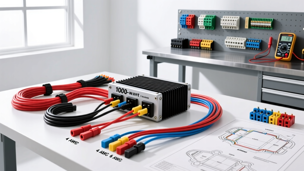
The Core Answer: What Gauge Wire for a 1000 Watt Amp?
When car audio enthusiasts and professional installers ask what gauge wire for 1000 watt amp systems is required, the definitive answer for a standard 12-volt automotive electrical system is 4 AWG Oxygen-Free Copper (OFC) for both the main power and ground runs. This specification assumes the amplifier is rated for 1000 watts RMS (Root Mean Square), not peak power, and that the total wire run from the battery to the amplifier and back to the ground point is under 20 feet.
Using the correct American Wire Gauge (AWG) is not just about preventing voltage drop; it is a critical safety measure. Undersized wiring in a high-current mobile audio environment can lead to thermal runaway, melted insulation, and catastrophic vehicle fires. According to the SAE J1128 standard for low-tension primary cable, a 4 AWG copper conductor is rated to safely handle up to 125 amps in a chassis wiring configuration, providing a safe buffer for high-draw audio equipment.
Understanding the Math: RMS Power and Efficiency
To understand why 4 AWG is the benchmark, we must calculate the actual current draw (amperage) of the amplifier. Many consumers confuse 'Peak Power' with 'RMS Power'. A 1000W peak amplifier might only produce 500W RMS. For this guide, we are sizing for a true 1000W RMS Class D monoblock or multi-channel amplifier.
- Base Current Draw: 1000 Watts / 12.5 Volts (average alternator output) = 80 Amps.
- Efficiency Factor: Class D amplifiers are typically 80% efficient. Therefore, the amplifier must pull more power from the battery to produce 1000W of acoustic output.
- Total Max Draw: 80 Amps / 0.80 (efficiency) = 100 Amps peak draw.
A 100A peak draw falls comfortably within the 125A safety threshold of 4 AWG OFC wire. However, if you are running a Class AB amplifier (which operates at roughly 50-60% efficiency), your max draw could exceed 150 Amps, necessitating an upgrade to 1/0 AWG wiring or a dual-amplifier distribution setup.
The Critical Distinction: OFC vs. CCA Wiring
When shopping for an amp wiring kit, you will encounter two materials: Oxygen-Free Copper (OFC) and Copper-Clad Aluminum (CCA). Never use 4 AWG CCA for a 1000W amplifier. Aluminum has approximately 61% the conductivity of copper. To carry the same 100A current safely, CCA wire must be roughly 40% thicker. If you are forced to use CCA wiring due to budget constraints, you must step up to 2 AWG to match the current-carrying capacity of 4 AWG OFC. For professional, reliable installations, OFC is the only acceptable standard.
Step-by-Step 1000W Amp Wiring Installation Guide
Step 1: Battery to Firewall (Power Wire Routing)
Begin by disconnecting the negative battery terminal. Route the 4 AWG Red OFC power wire from the positive battery post, through the engine bay, and into the cabin.
- Fusing: Install a 120A ANL or Class T fuse within 18 inches of the battery positive terminal. This protects the entire length of the wire in the event of a short circuit to the chassis.
- Firewall Penetration: Never drill a new hole in the firewall if a factory grommet is available. Use a blunt awl to pierce an existing rubber grommet, feed the wire through, and seal it with silicone RTV to prevent exhaust fumes and moisture from entering the cabin.
- Termination: Use a hydraulic crimper to attach a 4 AWG ring terminal. Seal the connection with 3:1 ratio adhesive-lined heat shrink to prevent moisture ingress and copper oxidation.
Step 2: Grounding the Amplifier (The Most Critical Step)
A 1000W amplifier will fail or enter protect mode if the ground is compromised. The ground wire must be 4 AWG Black OFC and no longer than 18 inches from the amplifier's ground terminal to the chassis.
- Locate a solid, structural piece of the vehicle's chassis (avoid seatbelts bolts or thin sheet metal).
- Use a wire brush or 80-grit sandpaper to remove all paint, primer, and clear coat down to bare, shiny metal.
- Attach the 4 AWG ground ring terminal using an M8 or M10 factory bolt. Torque the bolt to 15-20 Nm using a calibrated torque wrench to ensure a gas-tight connection without stripping the threads.
- Apply a thin layer of anti-oxidant dielectric grease over the terminal to prevent galvanic corrosion between the copper and the steel chassis.
Step 3: Remote Turn-On and RCA Routing
The remote turn-on wire signals the amplifier to power up when the head unit is on.
- Wire Spec: 18 AWG Blue/White stripe primary wire.
- Connection: Do not splice directly into the factory radio harness if possible. Instead, use an Add-A-Circuit (Fuse Tap) in the interior fuse box, tapping into a switched 12V accessory fuse (like the wipers or 12V accessory socket). Insert a 5A mini-fuse to protect the remote circuit.
- Signal Routing: Run your shielded RCA cables on the opposite side of the vehicle from the 4 AWG power wire to prevent electromagnetic interference (EMI), which manifests as alternator whine in the audio signal.
Step 4: Speaker Wire Sizing for Subwoofers
For a 1000W monoblock pushing high-excursion subwoofers, standard 16 AWG speaker wire is insufficient. Use 12 AWG or 10 AWG OFC speaker wire to minimize resistance between the amplifier's output terminals and the subwoofer's voice coils. This ensures maximum damping factor and tight, accurate bass response.
Technical Specification Chart: 1000W Amp Wiring Kit
| Component | Specification / AWG | Color Code | Max Length / Notes |
|---|---|---|---|
| Main Power Wire | 4 AWG OFC (Stranded) | Red | 15-20 ft max (from battery) |
| Main Ground Wire | 4 AWG OFC (Stranded) | Black | 18 inches max (to chassis) |
| In-Line Main Fuse | 120A ANL or Class T | N/A | Within 18 inches of battery (+) |
| Remote Turn-On Wire | 18 AWG Primary | Blue w/ White Stripe | 5A Fuse Tap recommended |
| Speaker Output Wire | 12 AWG OFC | Clear / Grey Stripe | Keep away from power wires |
| RCA Interconnects | Shielded Twisted Pair | Varies | Route opposite to power wire |
Reference: Sizing aligns with Crutchfield's Car Audio Wiring Guidelines and CTA-2015 mobile audio power standards.
Common Failure Modes & Troubleshooting
Even with the correct 4 AWG wire, improper installation techniques can mimic the symptoms of undersized wiring. Use this diagnostic tree to troubleshoot common 1000W amp issues:
- Symptom: Amp goes into 'Protect' mode during heavy bass hits.
- Cause: Voltage drop at the amplifier terminals.
- Fix: Measure voltage at the amp's B+ and GND terminals while playing a 40Hz test tone at 120dB. If voltage drops below 10.5V, check for loose ground bolts, corroded battery terminals, or an underperforming alternator. A 1000W draw may require a high-output alternator (e.g., 200A+) or a 2.5 Farad capacitor / Lithium battery bank.
- Symptom: Power wire is hot to the touch near the fuse holder.
- Cause: High resistance connection or undersized crimp.
- Fix: Cut off the terminal. Ensure you are using a ratcheting or hydraulic crimper designed for 4 AWG. A poorly compressed terminal creates a bottleneck that generates extreme heat (thermal compression failure).
- Symptom: High-pitched whine that increases with engine RPM.
- Cause: Ground loop or EMI induction.
- Fix: Verify that the head unit and the amplifier share a common ground potential. Ensure RCA cables are not zip-tied parallel to the 4 AWG red power wire. Cross power and signal wires at 90-degree angles if they must intersect.
Final Installation Advice
Answering the question of what gauge wire for 1000 watt amp builds is only the first step. The reliability of your mobile audio system depends entirely on the quality of your terminations, the purity of your copper, and the integrity of your chassis ground. Always invest in a premium 4 AWG OFC wiring kit, use adhesive-lined heat shrink on every exposed copper strand, and torque your hardware to manufacturer specifications. For further reading on automotive electrical standards, consult the Consumer Technology Association (CTA) mobile electronics guidelines.