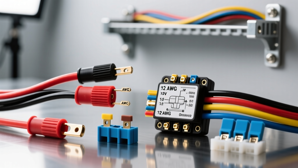
The 12V Paradigm: Why Household Rules Fail on Vehicles
Wiring exterior holiday lighting on a Jeep Wrangler, work truck, or RV requires a fundamental shift in electrical thinking. When enthusiasts search for the correct christmas light wire gauge, they often mistakenly apply 120V AC household rules to a 12V DC automotive environment. In a household setup, a thin 18 AWG or 20 AWG zip cord can safely carry the load of hundreds of LED bulbs because the high voltage keeps the amperage draw exceptionally low. However, in a 12V DC automotive system, the amperage draw is significantly higher for the same wattage, making voltage drop and heat generation critical failure points.
Whether you are routing custom 12V C7 incandescent bulb strings along a truck bed rail or wrapping an RV awning in high-density 12V LED strips, selecting the proper automotive wire gauge and integrating a robust relay-based wiring diagram is non-negotiable. This guide provides a complete wiring diagram walkthrough, specification charts, and real-world troubleshooting insights tailored specifically for vehicle-mounted holiday lighting.
Selecting the Proper Christmas Light Wire Gauge
Automotive primary wire must meet strict standards for insulation and current capacity. According to SAE J1128 specifications, wire insulation must withstand engine bay temperatures, chemical exposure, and abrasion. For exterior holiday lighting, you should always use cross-linked polyethylene (XLPE) insulated wire (often labeled as GXL or TXL) rather than standard PVC, especially if routing near exhaust components or the engine block.
AWG Specification Chart for 12V Holiday Lighting
| AWG Size | Max Ampacity (Chassis) | Resistance (Ohms/1000ft) | Recommended Automotive Application |
|---|---|---|---|
| 12 AWG | 41 Amps | 1.59 | Main power feed from battery to relay (Pin 30) for heavy incandescent loads. |
| 14 AWG | 32 Amps | 2.52 | Relay load output (Pin 87) to primary distribution block for multi-string setups. |
| 16 AWG | 22 Amps | 4.01 | Medium LED strip runs (up to 15ft) and secondary distribution branches. |
| 18 AWG | 16 Amps | 6.38 | Relay trigger circuit (Pins 85/86) and dash switch wiring. |
Note: Ampacity ratings are based on chassis wiring (short runs in free air). If bundling multiple wires inside a loom or conduit, you must derate the ampacity by at least 20% to account for trapped heat.
Complete Wiring Diagram Walkthrough: Relay & Fuse Integration
Never wire automotive Christmas lights directly to a dashboard switch or an existing tail light circuit. The factory wiring harness is engineered for specific OEM loads; adding holiday lighting can overload the Body Control Module (BCM) or melt factory traces. Instead, use a standard ISO Mini (Bosch-style) 4-pin automotive relay to isolate the high-current lighting load from the low-current trigger switch. For detailed relay specifications and internal schematics, refer to the Littelfuse Automotive Relay Catalog.
Circuit 1: The High-Current Power Feed (Pin 30 & Pin 87)
Pin 30 (Constant 12V+ Input): Run a 12 AWG red wire directly from the positive battery terminal to Pin 30 on the relay. Within 6 inches of the battery post, install an inline ATO/ATC blade fuse holder. For a standard 12V LED Christmas light setup drawing 10 amps, use a 15A fuse. For incandescent setups drawing 25 amps, use a 30A fuse and upgrade to 10 AWG wire.
Pin 87 (Switched 12V+ Output): Run a 14 AWG red wire from Pin 87 to a weather-sealed distribution block mounted in the engine bay or truck bed. From this block, you will branch out to your individual light strings. Using a distribution block prevents the need to crimp multiple ring terminals onto a single relay spade, which is a common cause of arcing and localized melting.
Circuit 2: The Low-Current Trigger (Pin 86 & Pin 85)
Pin 86 (Switch Input): Use 18 AWG wire. Run this from an ignition-switched 12V source (like a fuse box add-a-circuit) through a weather-sealed toggle switch on the dash or a wireless RF receiver module. This ensures your Christmas lights cannot be accidentally left on when the vehicle is parked, preventing a dead battery.
Pin 85 (Ground): Use 18 AWG black wire. Route this to a clean, bare-metal chassis ground point. Always use a ring terminal, secure it with a stainless steel bolt and star washer, and coat the connection in dielectric grease to prevent galvanic corrosion.
Circuit 3: The Lighting Load & Grounding
From your distribution block, run 16 AWG wire to the positive leads of your 12V Christmas lights. The ground wires for the lights should be terminated at local, dedicated ground points near the mounting location (e.g., truck bed tie-downs or Jeep tub bolts) rather than running ground wires all the way back to the battery. This halves the total wire length, significantly reducing voltage drop.
Connector Selection and Environmental Sealing
The harsh environment of a vehicle exterior demands professional-grade connections. Twist-and-tape methods will fail within weeks due to vibration and moisture ingress.
- Deutsch DT Connectors: Ideal for connecting the main power harness to removable light strings. They feature silicone seals and lock securely, handling up to 13 amps per contact (perfect for 14-16 AWG wire).
- Weather-Pack (Delphi/Aptiv): Excellent for the relay harness and dashboard switch integration. The ribbed barrel seals provide superior moisture resistance.
- Marine-Grade Heat Shrink Butt Splices: Use 3:1 shrink ratio adhesive-lined heat shrink for any inline splices on the light strings themselves. The internal meltable adhesive creates a waterproof bond that prevents copper oxidation.
Voltage Drop Calculations for Long Truck Beds and RVs
Voltage drop is the silent killer of 12V holiday lighting. If you run 40 feet of wire to the back of a long-bed truck or an RV bumper, an undersized wire will result in dim lights at the end of the run and excessive heat at the relay. The formula for DC voltage drop is:
VD = (2 x L x I x R) / 1000
Where L is one-way wire length in feet, I is current in amps, and R is wire resistance per 1000 ft.
Example Scenario: You are running a 20-foot one-way run (40 feet total loop) of 16 AWG wire (Resistance = 4.01 ohms/1000ft) to a heavy-duty 12V incandescent Christmas light string drawing 8 Amps.
VD = (2 x 20 x 8 x 4.01) / 1000 = 1.28 Volts.
Your lights will receive 10.72V instead of 12V. While LEDs might handle this, incandescent bulbs will appear noticeably dim and draw even more current as they struggle to reach operating temperature, creating a thermal runaway loop. In this scenario, upgrading to 12 AWG wire drops the voltage loss to a negligible 0.50V.
Real-World Troubleshooting and Failure Modes
Even with the correct christmas light wire gauge, installation errors can cause system failures. Here is a diagnostic decision tree for common issues:
Symptom: Lights flicker when driving over bumps
- Cause: Vibration is breaking a poor crimp connection, or a relay is unseating from a low-quality socket.
- Fix: Inspect all open-barrel crimps. Ensure you are using a ratcheting crimp tool (like the Delphi or IWISS ratcheting crimpers) rather than pliers. Replace the relay socket with a ceramic-reinforced pigtail if the plastic housing shows signs of heat warping.
Symptom: The inline fuse blows immediately upon switching on
- Cause: A dead short to ground on the load side (Pin 87), or an inrush current spike from large capacitive LED drivers.
- Fix: Disconnect the lights at the distribution block. Use a multimeter to test continuity between the load wire and the chassis. If it reads near zero ohms, trace the wire for pinched insulation (common where wires pass through metal truck bed grommets). If the wiring is intact, upgrade to a slow-blow (time-delay) fuse to handle the initial LED inrush current.
Symptom: Relay clicks rapidly or gets extremely hot
- Cause: Undersized wire on Pin 30 or Pin 87 causing high resistance, or a failing relay coil.
- Fix: Verify that the main power and load wires are at least 14 AWG. Check the spade terminals for corrosion or looseness. A loose terminal increases resistance, generating heat that transfers directly into the relay coil, causing it to fail prematurely.
Summary of Best Practices
Successfully wiring automotive exterior holiday lighting requires respecting the physics of 12V DC power. By utilizing the correct christmas light wire gauge (12-14 AWG for main feeds, 16-18 AWG for triggers), isolating the circuit with a Bosch-style relay, and sealing all connections with automotive-grade Deutsch or Weather-Pack connectors, you ensure a safe, reliable, and brilliant holiday display that can withstand the rigors of the road. Always route wiring through factory firewall grommets, secure looms with UV-resistant zip ties every 12 inches, and protect all bare metal connections with dielectric grease.