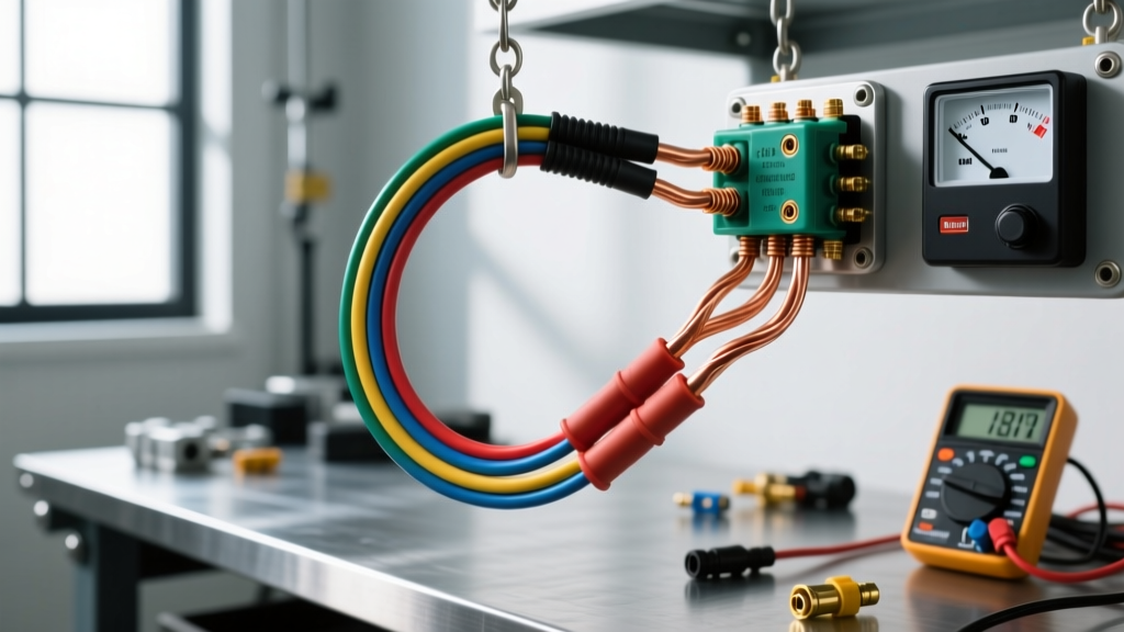
When building custom harnesses, installing aftermarket accessories, or repairing factory looms, 16 AWG is arguably the most frequently used wire size for low-draw automotive circuits. It is the undisputed workhorse for tail lights, dash illumination, ECU sensor grounds, and relay trigger signals. However, the ubiquity of 16 AWG wire leads to a dangerous complacency among DIYers and even some professional installers. The most common question we encounter is regarding the true 16 gauge wire amps 12 volt capacity, and the answers found on generic internet forums are often dangerously inaccurate.
Pushing 16 AWG wire beyond its safe thermal and electrical limits in a 12-volt automotive environment doesn't just cause dim lights or erratic sensor readings; it causes melted insulation, parasitic draws, and catastrophic electrical fires. In this comprehensive gauge reference guide, we will dissect the most critical safety mistakes made when calculating 16 gauge wire amps in 12 volt systems, providing actionable, expert-level guidance to ensure your vehicle's electrical system remains safe and reliable.
The Reality of 16 Gauge Wire Amps in 12 Volt Systems
Before we address the mistakes, we must establish the baseline physics. According to standard copper wire specifications, 16 AWG wire has a resistance of approximately 4.016 ohms per 1,000 feet. In a theoretical, free-air environment at room temperature, standard PVC-insulated 16 AWG wire can handle up to 13 to 15 amps before the insulation begins to degrade or melt.
However, an automobile is not a free-air, room-temperature environment. Under-hood temperatures routinely exceed 200°F (93°C), and wires are rarely routed alone. They are bundled into harnesses, wrapped in corrugated loom, and pushed behind dashboards with zero airflow. Therefore, the real-world continuous ampacity of 16 gauge wire amps 12 volt applications is significantly lower than the theoretical maximum. For continuous loads in an automotive chassis environment, the safe operating limit for 16 AWG is generally considered to be 8 to 10 amps.
Critical Mistake #1: Ignoring SAE J1128 vs. Standard AWG Derating
One of the most severe mistakes installers make is assuming all 16 AWG wire is created equal. Hardware store 16 AWG wire is typically rated for standard building wire (THHN/THWN) or basic PVC primary wire (SAE J1128 Type GPT). GPT wire is rated for a maximum continuous temperature of 80°C to 105°C. If you route GPT 16 AWG wire near an exhaust manifold or a turbocharger downpipe, the ambient heat alone will drastically reduce its current-carrying capacity (ampacity).
Automotive electrical experts mandate the use of cross-linked polyethylene (XLPE) insulated wires, specifically SAE J1128 Type GXL, TXL, or SGX. These wires feature a much thinner, tougher insulation wall and are rated for 125°C (GXL/TXL) or 150°C (SGX). While the copper core is identical, the superior thermal properties of TXL/GXL wire allow it to safely dissipate heat faster, maintaining a safer 16 gauge wire amps 12 volt rating in high-heat engine bays. Using standard PVC wire under the hood is a critical safety violation that leads to brittle, cracking insulation and subsequent short circuits.
Critical Mistake #2: Sizing Fuses to the Accessory, Not the Wire
A fundamental rule of automotive electrical safety is that the fuse protects the wire, not the accessory. A frequent and dangerous mistake occurs when an installer connects a 12-amp accessory (like a small air compressor or a high-draw LED light bar) to a 16 AWG wire and installs a 15-amp fuse because "the accessory needs 12 amps."
If that 16 AWG wire is routed 15 feet from the battery to the accessory and 15 feet back to the chassis ground (a 30-foot total circuit), the resistance of the wire will cause a voltage drop. To push 12 amps through that resistance, the wire must dissipate excess energy as heat. At 15 amps, a 16 AWG wire in a bundled harness will overheat long before the 15-amp fuse blows. The insulation will melt, shorting against the chassis and potentially starting a fire.
16 AWG Fuse and Voltage Drop Reference Chart (12V Nominal System)
The following table illustrates the real-world voltage drop and recommended maximum continuous fuse sizing for 16 AWG automotive wire (assuming TXL/GXL cross-linked copper) in a 12.6V charging system.
| Wire Length (One Way) | Total Circuit Length (x2) | Circuit Resistance (Ohms) | Voltage Drop @ 8 Amps | Voltage Drop @ 10 Amps | Max Recommended Fuse |
|---|---|---|---|---|---|
| 5 Feet | 10 Feet | 0.040 Ω | 0.32V | 0.40V | 10 Amp (Continuous) |
| 10 Feet | 20 Feet | 0.080 Ω | 0.64V | 0.80V | 10 Amp (Continuous) |
| 15 Feet | 30 Feet | 0.120 Ω | 0.96V | 1.20V | 7.5 Amp (Continuous) |
| 20 Feet | 40 Feet | 0.160 Ω | 1.28V | 1.60V | 7.5 Amp (Continuous) |
Note: If your accessory requires more than 8-10 amps, or if the run exceeds 10 feet, you must step up to 14 AWG or 12 AWG wire. Never force 16 gauge wire amps 12 volt limits to accommodate high-draw loads.
Critical Mistake #3: Tapping Factory Harnesses for High-Draw Accessories
Modern vehicles use highly optimized, multiplexed wiring harnesses. Factory engineers use 16 AWG (and often 18 or 20 AWG) for circuits that draw minimal current. A classic example is the OBD-II diagnostic port. Pin 16 on the OBD-II connector provides constant 12V battery power, typically wired with 16 AWG or 14 AWG wire, fused at 15A or 20A at the main fuse block.
Many enthusiasts tap into this Pin 16 circuit to power radar detectors, tuning interfaces (like HP Tuners or Cobb Accessports), or auxiliary gauge pods. While these devices usually draw less than 3 amps, problems arise when installers tap into the factory 16 AWG tail light wire (usually Brown for parking lights or Dark Green for right turn/stop signals) to trigger high-draw trailer modules or off-road LED pods. The factory 16 AWG wire and its associated 10A or 15A BCM (Body Control Module) fuse cannot handle the sudden inrush current of multiple LED drivers or incandescent trailer bulbs. This leads to melted BCM pins, blown fuses, and in severe cases, damaged control modules that cost thousands of dollars to replace.
Real-World Failure Mode: The Melted Headlight Switch Harness
A notorious example of 16 AWG overload occurs in older GM trucks (1999-2006 Silverado/Sierra). The factory headlight switch harness routes high-beam and daytime running light (DRL) currents through the dash switch. Over time, the continuous 10-12 amp draw through the 16 AWG and 14 AWG switch wires, combined with resistance from oxidized switch contacts, generates enough heat to literally melt the plastic switch housing and the wire insulation. The proper fix is not to replace the switch, but to install a heavy-duty headlight relay harness that uses 12 AWG wire for the main power and limits the factory 16 AWG switch wire to a low-draw trigger signal (under 1 amp).
Proper Termination: Where 16 AWG Connections Actually Fail
Even if you correctly calculate your 16 gauge wire amps 12 volt requirements, a poor termination will create a high-resistance bottleneck that generates localized heat. When working with 16 AWG wire, you must use the correct terminals and crimping tools.
- Delphi (Aptiv) Weather-Pack: For 16 AWG wire, you must use the 16-14 AWG terminal range (e.g., Male Terminal Part #12015771). Using the 20-16 AWG terminal on a thick 16 AWG wire will result in stripped strands and a weak crimp.
- Deutsch DT Connectors: When using solid open-barrel contacts, ensure your crimp die is set precisely for 16 AWG. An over-crimp will cut the copper strands; an under-crimp will allow the wire to pull out under vibration.
- Crimp vs. Solder: In high-vibration automotive environments, soldering 16 AWG wire directly to a terminal is discouraged. Solder wicks into the wire strands, creating a rigid section that will fatigue and snap under engine vibration. Always use a high-quality ratcheting crimp tool, followed by adhesive-lined dual-wall heat shrink tubing to seal out moisture and prevent corrosion.
Expert Troubleshooting: Diagnosing 16 Gauge Voltage Drop
If you suspect a 16 AWG circuit is overloaded or suffering from excessive voltage drop, do not rely on visual inspection. The insulation may look fine while the copper inside is annealing and losing conductivity. Perform this step-by-step multimeter test:
- Set your multimeter to DC Volts (20V range).
- Turn on the accessory to place the circuit under its maximum continuous load.
- Measure at the source: Place the red probe on the positive battery terminal and the black probe on the negative battery terminal. Note the baseline voltage (e.g., 13.8V with the engine running).
- Measure at the load: Back-probe the connector at the accessory itself while it is operating. Place the red probe on the 12V supply pin and the black probe on the ground pin.
- Calculate the drop: Subtract the load voltage from the source voltage. If your baseline is 13.8V and the accessory is seeing 11.5V, you have a 2.3V drop. For a 16 AWG circuit, any drop exceeding 0.5V to 0.8V indicates the wire is undersized for the amperage, the run is too long, or there is severe corrosion at a termination point.
For more detailed wiring schematics and connector pinouts, refer to OEM service manuals or trusted aftermarket resources like Painless Performance Products wiring guides, which provide excellent baseline data for chassis wiring limits.
Final Safety Verdict
Respecting the physical limitations of 16 gauge wire amps 12 volt systems is non-negotiable for automotive electrical safety. Limit 16 AWG to 8-10 amps maximum for continuous loads, use SAE J1128 cross-linked wire in engine bays, size your fuses to protect the wire (not the accessory), and always utilize relays for high-draw components. By avoiding these common mistakes, you ensure your vehicle's electrical system operates efficiently, safely, and reliably for years to come.