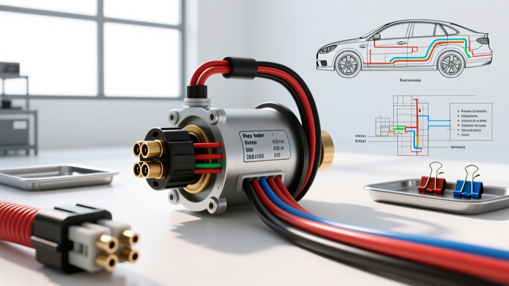
Introduction to Air Brake Dryer Electrical Systems
When winter temperatures plummet, the air brake system on heavy-duty trucks faces severe moisture and freezing risks. The air dryer purge valve, a critical component in systems like the Bendix AD-IS or Wabco System Saver, utilizes an integrated electrical heater to prevent the exhaust port from freezing open. A frequent cause of purge valve failure—and subsequent air system contamination—is an incorrect dryer wire gauge or degraded wiring harness. When technicians replace a melted harness or blown fuse, they often default to whatever wire is on the bench. However, applying standard passenger car wiring logic to a commercial truck's 15-amp continuous heater circuit guarantees repeat failures. This guide provides a step-by-step troubleshooting flow and exact wire gauge specifications to ensure your air dryer purge valve operates flawlessly under extreme thermal and electrical loads.
SAE J1128 Wire Gauge & Ampacity Reference Chart
Automotive wiring must comply with SAE J1128 Low Tension Primary Cable standards. For air dryer heaters, Cross-Linked Polyethylene (XLPE) insulated wire, specifically GXL or TXL, is mandatory due to the high ambient temperatures near the engine block and chassis rails. The heater element in a standard 12V commercial truck air dryer draws between 10 and 14 amps continuously during the purge cycle. Below is the reference chart for selecting the proper wire gauge based on circuit length and system voltage.
| System Voltage | Max Current Draw | Run Length (One Way) | Recommended AWG (GXL/TXL) | Max Voltage Drop Allowance |
|---|---|---|---|---|
| 12V Nominal | 14.0 Amps | Under 10 Feet | 12 AWG | 0.5V (approx 4%) |
| 12V Nominal | 14.0 Amps | 10 to 25 Feet | 10 AWG | 0.4V (approx 3%) |
| 24V Nominal | 7.0 Amps | Under 20 Feet | 14 AWG | 0.8V (approx 3%) |
| 24V Nominal | 7.0 Amps | 20 to 40 Feet | 12 AWG | 0.6V (approx 2.5%) |
Note: Always calculate run length from the battery distribution block or fuse panel to the air dryer, and back to the chassis ground point. If the total circuit loop exceeds 25 feet on a 12V system, stepping up to 8 AWG is highly recommended to prevent voltage starvation at the heater element.
Step-by-Step Troubleshooting Flow: Purge Valve Heater Circuit
Follow this diagnostic decision tree when diagnosing a blown air dryer fuse, a purge valve that fails to cycle, or an exhaust port that is icing over in sub-freezing conditions.
Step 1: Verify the Fuse and In-Rush Current
Air dryer heaters are resistive loads, but cold heating elements exhibit a lower initial resistance, causing a brief in-rush current spike that can be 15-20% higher than the steady-state draw. If the circuit is protected by a standard 15A ATO blade fuse, it may nuisance-blow during extreme cold starts.
- Action: Inspect the fuse panel. If a 15A fuse is blown and the wiring is verified at 10 AWG or 12 AWG, replace it with a 20A Slow-Blow (Time-Delay) fuse or a MEGA fuse if located at the main distribution post, per Littelfuse heavy-duty circuit protection guidelines.
- Warning: Never upsize a fuse without first verifying that the dryer wire gauge can handle the increased continuous amperage. Upsizing a fuse on a 14 AWG wire is a severe fire hazard.
Step 2: Perform a Loaded Voltage Drop Test
A multimeter reading 12.4V at the connector with the key off tells you nothing about the circuit's health under load. You must test for voltage drop while the heater is actively drawing current.
- Turn the ignition to the ON position (engine off) to energize the air dryer heater circuit. Some systems require the engine to be running and the air compressor to be actively building pressure before the purge valve ECU grounds the heater.
- Set your digital multimeter (DMM) to DC Volts.
- Place the positive probe on the battery positive post and the negative probe on the power pin at the air dryer connector (back-probe carefully to avoid spreading the terminal).
- Read the voltage drop on the positive side. A reading greater than 0.5V indicates excessive resistance, usually caused by an undersized wire gauge, corroded bulkhead connectors, or a failing ignition relay.
- Repeat the test on the ground side: Positive probe on the battery negative post, negative probe on the air dryer ground pin. A drop greater than 0.2V on the ground side indicates a poor chassis ground.
Step 3: Test Heater Element Resistance
If the wiring and voltage supply are confirmed, isolate the air dryer purge valve heater element itself. Disconnect the harness and set the DMM to Ohms.
- 12V Systems: Expect a resistance reading between 0.8 and 1.2 Ohms. (Using Ohm's Law: R = V/I. 12V / 12A = 1.0 Ohm).
- 24V Systems: Expect a resistance reading between 3.0 and 4.5 Ohms.
- Diagnostic Result: If the meter reads 'OL' (Open Line), the internal heating element is burnt out, and the entire purge valve assembly must be replaced. If it reads near 0.0 Ohms, the element is internally shorted, which explains the blown fuse.
Step 4: Inspect Metri-Pack 280 Connector Integrity
Heavy-duty trucks utilize Delphi (Aptiv) Metri-Pack 280 series connectors for high-current under-hood components. The wide 2.8mm blade terminals are designed for 15-20 amp circuits.
- Check for Terminal Spread: If a previous technician forced a probe into the front of the connector, the female terminals may be spread, causing a loose connection that arcs and melts the plastic housing.
- Check for Green Copper Oxide: Moisture ingress leads to capillary action, drawing water up into the wire insulation. If you see green corrosion on the copper strands inside the crimp barrel, cut the wire back at least 12 inches to clean copper before splicing in new GXL wire.
Air Dryer Purge Valve Connector Pinout Reference
Modern integrated air dryers (like the Bendix AD-IS) feature multi-pin connectors that handle both the high-current heater and the low-current solenoid or thermistor signals. Below is the standard 3-pin Metri-Pack configuration:
| Pin Cavity | Wire Color (Typical) | Circuit Function | Wire Gauge Requirement |
|---|---|---|---|
| Pin A | Red | Heater Power (12V/24V Ignition) | 10 AWG or 12 AWG (GXL) |
| Pin B | Black | Heater Ground / Common Ground | 10 AWG or 12 AWG (GXL) |
| Pin C | White or Light Green | Thermistor Signal to ECU | 18 AWG (TXL) |
Always refer to the specific OEM wiring schematic for your truck model (e.g., Freightliner Cascadia or Volvo VNL), as European manufacturers may use DIN-standard wire colors (e.g., Red/White for switched power, Brown for ground).
Best Practices for Harness Repair and Splicing
When repairing an air dryer harness due to chafing against the chassis rail or firewall, never use standard vinyl electrical tape or twist-and-solder methods. The vibration profile of a heavy-duty diesel engine will fracture rigid solder joints within months.
- Use Adhesive-Lined Heat Shrink: All splices must be sealed with dual-wall, adhesive-lined polyolefin heat shrink tubing to prevent moisture intrusion.
- Open Barrel Crimps: Use a proper ratcheting open-barrel crimp tool for Metri-Pack terminals. The crimp must feature a distinct wire grip (for electrical conductivity) and an insulation grip (for strain relief).
- Loom and Secure: Route the repaired harness away from the exhaust manifold and turbocharger. Secure with high-temperature nylon cable ties every 8 inches, and wrap the harness in split-loom tubing or Tesa fleece tape to prevent abrasion against the air tank brackets.
Summary and Technical Resources
Ensuring the correct dryer wire gauge and maintaining terminal integrity is the difference between a reliable winter run and a tow-truck call due to frozen air brakes. By adhering to SAE J1128 standards, performing loaded voltage drop tests, and utilizing proper heavy-duty crimping techniques, you guarantee the air dryer purge valve receives the stable voltage it requires to keep the air system dry and operational. For further reading on commercial vehicle air system schematics, consult the Bendix Commercial Vehicle Systems technical document library and your specific OEM body builder wiring manuals.