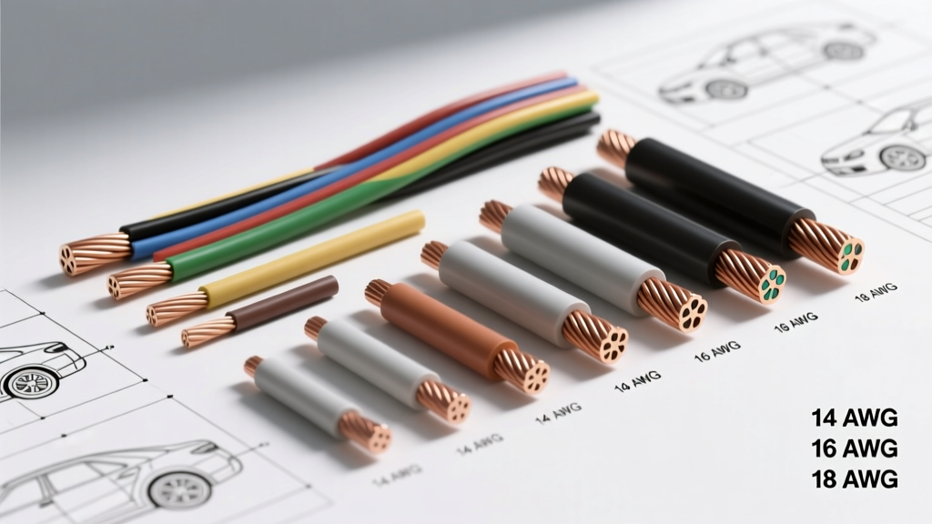
Decoding Automotive Wire Gauge Dia: Bare Copper vs. Overall Diameter
Selecting the appropriate wire gauge dia (diameter) is the most critical decision in automotive electrical system design. Whether you are repinning a GM Gen IV LS ECM connector or routing high-amperage alternator cables through the firewall of a classic muscle car, misunderstanding the relationship between American Wire Gauge (AWG) sizing, bare copper diameter, and overall outside diameter (O.D.) can lead to catastrophic voltage drop, melted insulation, or terminal push-out. In automotive wiring, 'wire gauge dia' actually refers to two distinct measurements: the bare copper conductor diameter and the total outside diameter including the insulation jacket.
The bare copper diameter dictates the electrical resistance and ampacity of the circuit. For instance, a standard 12 AWG copper conductor measures exactly 0.0808 inches (2.05 mm) in diameter, providing a cross-sectional area of 3.31 mm². However, when purchasing wire, the overall wire gauge dia determines which loom size, grommet, and connector cavity you must use. A 12 AWG wire with thick SXL insulation will have a vastly different overall diameter than a 12 AWG wire with thin-wall TXL insulation, fundamentally changing how it interfaces with Deutsch DT or Metri-Pack 2.8 connector housings.
Insulation Chemistry: GXL vs. TXL vs. SXL Comparison
Modern automotive harnesses rely on cross-linked polyethylene (XLPE) insulation, governed by the SAE J1128 standard. Unlike older PVC wires that melt at relatively low temperatures, XLPE wires can withstand continuous engine bay temperatures up to 125°C to 150°C. When comparing products for your build, you must choose between three primary insulation profiles, each altering the final wire gauge dia:
TXL (Thin-Wall Cross-Linked)
TXL features the thinnest insulation wall among the three. It is the industry standard for modern OEM engine harnesses where space and weight are at a premium. Because the insulation is thin, the overall wire gauge dia is minimized, allowing for tighter bend radii and easier routing through crowded firewall grommets and narrow dashboard channels. TXL is ideal for low-to-medium current sensor circuits and interior cabin wiring.
GXL (General Purpose Cross-Linked)
GXL is the most common aftermarket automotive wire. It offers a medium-thickness insulation wall, providing an excellent balance between flexibility, abrasion resistance, and overall diameter. When building a custom chassis harness or replacing degraded factory wiring in a daily driver, GXL is typically the default choice. Its overall wire gauge dia is slightly larger than TXL, requiring standard-sized terminal crimp barrels.
SXL (Special Cross-Linked)
SXL features the thickest insulation jacket. While it drastically increases the overall wire gauge dia, it provides maximum protection against high-heat environments, abrasion, and chemical exposure. SXL is mandatory for wiring routed near exhaust manifolds, turbocharger downpipes, or high-vibration areas where the wire may chafe against the chassis. The trade-off is reduced flexibility and a requirement for larger connector cavities.
Comprehensive Wire Gauge Dia and AWG Specification Chart
The following table contrasts the bare copper diameter with the overall outside diameter (O.D.) for GXL and TXL wire types. This reference is crucial when selecting the correct terminal crimp barrel and connector housing.
| AWG Size | Bare Copper Dia (in) | Bare Copper Dia (mm) | TXL Overall Dia (in) | GXL Overall Dia (in) | Max Ampacity (Engine Bay) |
|---|---|---|---|---|---|
| 18 AWG | 0.0403 | 1.02 | 0.061 | 0.067 | 9 Amps |
| 16 AWG | 0.0508 | 1.29 | 0.074 | 0.080 | 13 Amps |
| 14 AWG | 0.0641 | 1.63 | 0.089 | 0.096 | 19 Amps |
| 12 AWG | 0.0808 | 2.05 | 0.110 | 0.118 | 28 Amps |
| 10 AWG | 0.1019 | 2.59 | 0.135 | 0.145 | 41 Amps |
| 8 AWG | 0.1285 | 3.26 | 0.167 | 0.180 | 58 Amps |
| 4 AWG | 0.2043 | 5.19 | 0.255 | 0.275 | 110 Amps |
Application-Specific Selection Guide
High-Current Charging and Starter Circuits (4 AWG to 1/0 AWG)
For high-amperage circuits like the starter motor, alternator output, and main battery feeds, minimizing voltage drop is paramount. A standard V8 starter can draw 150 to 200 amps under cranking load. Using undersized wire here will starve the ignition system of voltage, causing hard starts. For runs under 5 feet, 4 AWG GXL or SXL wire is the minimum acceptable standard. If the battery is relocated to the trunk, you must step up to 1/0 AWG to compensate for the extended run length.
When terminating 4 AWG or larger wire, avoid open-barrel crimps. Use closed-barrel copper lugs with an adhesive-lined dual-wall heat shrink (such as 3M FP-301). The heat shrink must seal entirely over the insulation jacket to prevent moisture ingress, which causes green copper corrosion and increases resistance over time. Always torque the starter stud nut to the manufacturer's specification—typically 12 to 15 lb-ft for a standard 3/8-16 stud—to ensure the ring terminal makes full contact without crushing the wire strands.
ECU Pinouts and Low-Current Sensor Networks (18 AWG to 22 AWG)
Modern Engine Control Units (ECUs) rely on low-current, high-fidelity signals from sensors like the Mass Air Flow (MAF), Manifold Absolute Pressure (MAP), and wideband O2 sensors. These circuits require 20 AWG or 22 AWG TXL wire. The thin insulation of TXL allows multiple wires to fit into the dense, multi-row cavities of connectors like the Delphi GT 280 or the Bosch Motronic series.
When crimping 20 AWG TXL into a Metri-Pack 150 terminal, the wire gauge dia requires extreme precision. Stripping the wire must be done with calibrated micro-strippers to avoid nicking the 0.032-inch bare copper strands. A nicked strand creates a stress riser that will eventually snap under engine vibration. Furthermore, the terminal crimp height must be set exactly to 0.045 inches on your crimping die; over-crimping will cut the copper, while under-crimping will cause the wire to pull out of the terminal when inserting it into the plastic connector housing.
Real-World Failure Modes and Troubleshooting
Understanding the physical dimensions of your wire prevents several common automotive electrical failures:
- Terminal Push-Out: This occurs when the overall wire gauge dia (including insulation) is too large for the connector cavity's rear seal. If you attempt to force a 14 AWG GXL wire into a connector designed for 14 AWG TXL, the thick insulation will bind against the silicone weather seal. The terminal will not fully seat, causing the secondary lock (TPA) to fail and the pin to push out of the housing during mating.
- Insulation Melting and Shorting: Using standard PVC wire or thin-wall TXL too close to a turbocharger exhaust housing will result in the insulation melting. Once the bare copper is exposed, it shorts against the chassis, instantly blowing the main ECU fuse and potentially frying the injector driver circuit. Always mandate SXL wire with fiberglass sleeving in these high-heat zones.
- Hidden Voltage Drop: A wire may have the correct bare copper diameter, but if the terminal crimp was poorly executed, the connection point becomes a resistor. Use a digital multimeter to perform a voltage drop test across the crimped connection while the circuit is under load. A healthy crimp should show less than 0.05V drop; anything over 0.1V indicates a failing termination that requires cutting and re-crimping.
Authoritative References
For further engineering data on automotive wire specifications, terminal pull-out forces, and crimp validation, consult the following industry standards and resources: