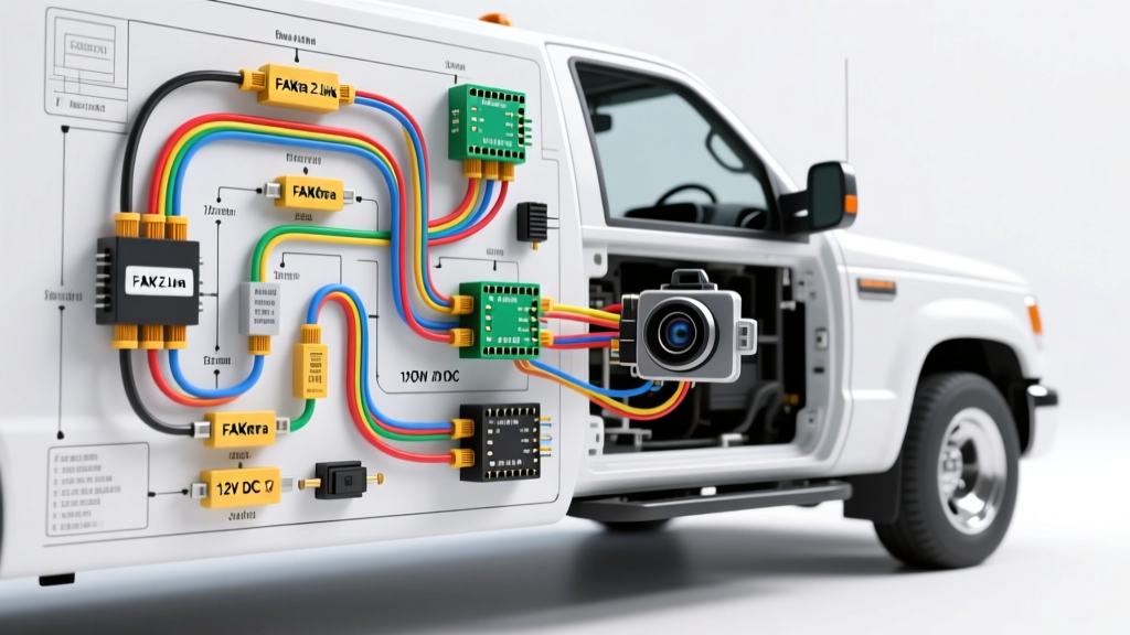
The Paradigm Shift in Advanced Camera Integration
Performing a new camera installation on a late-model (2018-2023) truck or SUV is no longer a simple matter of tapping a reverse light wire and running a composite video cable to the head unit. Modern vehicles utilize Pulse Width Modulation (PWM) for exterior lighting, multiplexed Body Control Modules (BCMs), and high-frequency FAKRA coaxial networks. If you approach a modern retrofit with legacy 12V DC assumptions, your system will suffer from rolling video, relay chatter, or complete BCM network faults. This advanced technical guide dissects the electrical architecture required to properly integrate an aftermarket or OEM-style HD camera into a PWM-controlled, CAN-bus-monitored environment.
PWM vs. DC: Why Your Reverse Trigger Fails
In legacy vehicles, placing the transmission in reverse closed a simple mechanical switch, sending a continuous 12V-14.4V DC signal to the reverse lamps. Modern architectures, particularly those by Ford and Stellantis (Ram/Jeep), use a TIPM (Totally Integrated Power Module) or BCM that outputs a PWM signal to the lighting circuits. This is done for two reasons: cold-diagnostic bulb checking (pulsing a low-voltage signal to measure resistance without illuminating the LED) and thermal management.
Oscilloscope Data: Reading the Reverse Lamp Circuit
When probing the reverse lamp wire on a 2019+ F-150 or Ram 1500 with an oscilloscope, you will not see a flat 12V line. Instead, you will observe a 500Hz to 1kHz square wave. During the initial 'bulb check' phase, the duty cycle may be as low as 10% (yielding ~1.2V RMS). When fully engaged, the duty cycle rises to roughly 80%, yielding an RMS voltage of approximately 10.8V. While 10.8V is sufficient to illuminate high-efficiency LEDs, it is often below the pull-in voltage threshold of a standard 12V automotive relay coil, causing the relay to chatter violently or fail to engage. Furthermore, feeding this noisy square wave directly into a camera's 'Reverse In' trigger pin will cause the head unit's video processor to rapidly cycle on and off, resulting in a flickering or 'no signal' display.
Designing the RC Filter Circuit
To execute a successful new camera installation in a PWM environment, you must convert the square wave into a smooth DC voltage. This is achieved using a passive Resistor-Capacitor (RC) low-pass filter followed by a flyback diode.
- Component 1 (Resistor): 470Ω 1/2W Metal Film Resistor. Placed in series with the PWM reverse light tap.
- Component 2 (Capacitor): 2200µF 25V Electrolytic Capacitor. Placed in parallel (positive to the resistor output, negative to chassis ground). This stores the charge during the PWM 'off' cycles.
- Component 3 (Diode): 1N4004 Rectifier Diode. Placed after the capacitor, with the cathode (stripe) facing the camera trigger wire to prevent back-feeding the BCM when the vehicle is shifted out of reverse.
This circuit smooths the 80% duty cycle PWM into a stable 10.5V - 11.2V DC output, providing a clean, chatter-free trigger signal for the camera's internal voltage regulator and the head unit's reverse-detect pin.
FAKRA Z-Link Coaxial Termination & Specifications
Standard RCA composite cables are obsolete in modern automotive video networks due to electromagnetic interference (EMI) from high-voltage ignition coils and alternator whine. OEM and high-end aftermarket systems use FAKRA connectors. For backup and 360-degree cameras, the Z-Code (Water Blue) connector is the industry standard, designated for 50-ohm impedance video and GPS applications.
According to TE Connectivity's FAKRA RF specifications, improper crimping of the coaxial shield will result in Return Loss (VSWR) issues, manifesting as ghosting or horizontal tearing on the head unit display.
FAKRA Crimping Protocol
- Jacket Stripping: Strip the outer PVC jacket to exactly 5.2mm. Do not nick the braided shield.
- Dielectric Flushness: The inner PTFE dielectric must sit exactly 0.5mm proud of the brass center pin crimp barrel. If recessed, the center pin will short against the outer housing.
- Center Pin Crimp: Use a micro-indent crimp die (e.g., IWISS IWS-FAKRA). The indent must be centered on the barrel, achieving a pull-force resistance of >30N as per SAE automotive cable termination standards.
- Ferrule Crimp: The outer hex ferrule must be crimped over the braided shield using a hex die measuring exactly 5.0mm across flats. This ensures the 360-degree EMI shield is bonded to the FAKRA outer housing.
4-Pin OEM Camera to FAKRA Z-Link Adapter Pinout
When adapting a salvaged OEM camera (which typically uses a proprietary waterproof 4-pin or 6-pin micro-connector) to a standard FAKRA Z-Link and trigger harness, precise pin mapping is critical. Reversing the Video- and Ground pins will result in a severely rolled image due to the disruption of the NTSC/PAL sync pulses.
| OEM 4-Pin Connector | Wire Color (Typical OEM) | FAKRA / Harness Destination | Signal Specification |
|---|---|---|---|
| Pin 1 | Red / White Stripe | 12V DC Source (Filtered) | 9.0V - 16.0V DC, Max 250mA |
| Pin 2 | Green / Yellow Stripe | FAKRA Z Center Conductor | Composite Video (+), 1Vp-p, 75Ω |
| Pin 3 | Black | FAKRA Z Outer Shield | Video Ground / EMI Shield |
| Pin 4 | Solid Black / Green | Chassis Ground (Local) | Logic Ground (0V Reference) |
CAN-Bus Integration & Gateway Waking
In vehicles equipped with Advanced Driver Assistance Systems (ADAS) or factory 360-degree modules, the camera is not just a passive video source; it is a network node. The BCM or Image Processing Module (IPM) expects to see a specific LIN-bus or CAN-bus handshake when the vehicle is shifted into reverse. If you are bypassing the factory IPM to feed a signal directly to an aftermarket Android head unit, you must terminate the unused CAN-bus lines to prevent the vehicle's gateway from throwing a U-code (Network Fault).
According to NXP Semiconductor's automotive network guidelines, an unterminated CAN High (CAN-H) or CAN Low (CAN-L) line can act as an antenna, injecting noise into the High-Speed CAN (HS-CAN) bus. If your new camera harness includes CAN-H and CAN-L wires that are not being utilized by an aftermarket interface module, terminate them individually with heat-shrink end-caps and secure them away from the FAKRA coaxial run. Never bundle un-terminated CAN wires with the video coaxial, as the inductive coupling from the CAN bus differential signals (which toggle at up to 500kbps) will induce severe alternator whine and digital artifacts into the analog video signal.
Wire Gauge & Material Specifications
Do not use standard PVC-jacketed primary wire (GPT) for the 12V power run to the camera. The engine bay and rear fascia of modern trucks frequently exceed 105°C in direct summer sunlight. You must use TXL (Cross-linked polyethylene) wire. TXL features a thinner insulation wall, allowing for easier routing through tight factory grommets, and is rated for 125°C continuous operation.
- Power & Ground: 18 AWG TXL (Stranded, 16/30 construction).
- Video Coaxial: RG-174U or RG-316 (50-ohm, silver-plated copper center conductor to resist galvanic corrosion in the rear hatch environment).
Advanced Troubleshooting Decision Tree
| Symptom | Probable Cause | Diagnostic Action & Fix |
|---|---|---|
| Camera powers on, but image rolls vertically. | Video Ground (Pin 3) and Logic Ground (Pin 4) are shorted or swapped. | Check continuity between FAKRA outer shield and chassis. Ensure Video Ground is isolated from Logic Ground at the camera pigtail. |
| Head unit displays 'No Signal' and relay clicks rapidly. | PWM reverse trigger is unfiltered; relay coil is chattering. | Probe trigger wire with oscilloscope. If square wave is present, install the 470Ω/2200µF RC filter circuit. |
| Image has horizontal scrolling bars (alternator whine). | Ground loop or EMI coupling from CAN-bus/PWM lines. | Verify camera ground is tied to a clean chassis point, not the taillight ground. Separate FAKRA coax from PWM power wires by at least 4 inches. |
| BCM throws U0231 (Lost Comm with Rear Camera). | Factory IPM expects a LIN-bus handshake from the camera. | Install a LIN-bus emulator module, or use an OBDII gateway programmer to code out the rear camera from the BCM configuration. |
Conclusion
A successful new camera installation in the modern automotive era requires an electrical engineering mindset. By understanding the nuances of PWM lighting circuits, executing precision FAKRA Z-Link terminations, and respecting the vehicle's CAN-bus topology, you can achieve a glitch-free, OEM-quality video integration that withstands the harsh electrical and thermal environments of late-model trucks and SUVs.