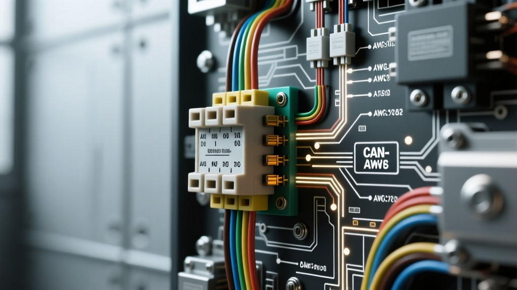
The Hidden Dangers of Covert Automotive Wiring
Executing a flawless hidden camera installation requires far more than simply tucking a lens behind a rearview mirror and routing a USB cable to the cigarette lighter. Whether you are integrating a discreet interior cabin camera for rideshare monitoring, a covert anti-theft sentry system, or a flush-mounted backup camera, tapping into a modern vehicle's 12V electrical architecture carries significant risks. Modern vehicles utilize multiplexed networks, sensitive body control modules (BCMs), and high-voltage safety systems. A single wiring error during a covert camera setup can trigger cascading electrical failures, parasitic battery drains, or worse, compromise the deployment of critical safety restraints.
This guide outlines the most dangerous mistakes made during hidden camera installations and provides the exact technical protocols required to ensure safety, reliability, and compliance with automotive electrical standards.
Mistake #1: Reverse-Polarity Fuse Taps (Add-A-Circuit)
The most common and destructive error in hidden camera wiring is the improper orientation of an Add-A-Circuit (fuse tap) in the interior fuse panel. Fuse panels are designed with a 'Line' (power source) side and a 'Load' (accessory) side. When a fuse tap is inserted backward, the newly added camera circuit bypasses the original fuse protecting the vehicle's factory accessory.
If your hidden camera is drawing power from a circuit shared with a critical module (such as the ABS controller, SRS airbag module, or CAN-Bus gateway), and the 18 AWG camera wire experiences a short to ground, the camera's low-amperage fuse (e.g., 3A or 5A) will blow. However, because the tap is reversed, the factory 20A or 30A fuse will not blow to protect the circuit. This forces the factory wiring harness to carry the short-circuit current, potentially melting the harness, damaging the BCM, or starting an electrical fire.
The Multimeter Verification Protocol
- Remove the target factory fuse from the panel.
- Set your digital multimeter (DMM) to DC Voltage.
- Connect the black probe to a known good chassis ground.
- Probe both empty fuse slots with the red probe. The slot that reads 12V (or switched 12V) is the Line side.
- The slot that reads 0V is the Load side.
- Insert the fuse tap so that the pigtail wire connects to the Load side slot, ensuring both the factory accessory and the new camera circuit are independently protected by their respective fuses.
Mistake #2: Tapping into CAN-Bus or SRS Circuits
When searching for a switched 12V ignition source behind the dashboard, installers frequently encounter twisted-pair wiring. These are Controller Area Network (CAN-Bus) cables, typically operating at 5V logic (CAN-High at ~2.5V to 3.5V, and CAN-Low at ~1.5V to 2.5V). Splicing into these wires to find a 'signal' or using them as a ground reference will introduce impedance mismatches and electrical noise.
Piercing the insulation of CAN-Bus wires with Scotch-Loks or T-taps compromises the 120-ohm termination resistance of the network. This results in U-codes (e.g., U0100 Lost Communication with ECM) and can put the vehicle into a fail-safe 'limp' mode. Furthermore, any wiring loom wrapped in yellow tubing or yellow connectors is part of the Supplemental Restraint System (SRS). Never route, zip-tie, or splice hidden camera wires near the SRS clock spring, side-curtain airbag deployment chutes, or seat-belt pretensioners. According to NHTSA safety guidelines, tampering with or obstructing SRS pathways can result in catastrophic failure during a collision.
Wire Gauge and Voltage Drop Specifications
Covert camera installations often require long wire runs from the rear hatch or trunk to the front fuse panel, sometimes exceeding 15 feet of total conductor length. Using undersized wire leads to severe voltage drop, causing the camera's internal voltage regulator to overheat or the device to reboot continuously when the vehicle's alternator is under load.
| Wire Gauge (AWG) | Max Current (Chassis Wiring) | Max Run Length @ 2A (12V System) | Common Application |
|---|---|---|---|
| 22 AWG | 3 Amps | ~4 Feet | Low-power interior cabin sensors |
| 20 AWG | 5 Amps | ~8 Feet | Standard 1080p dash cams |
| 18 AWG | 7 Amps | ~14 Feet | 4K hidden cameras with Wi-Fi/GPS |
| 16 AWG | 10 Amps | ~20+ Feet | Multi-channel sentry mode hardwire kits |
Note: Always use stranded copper wire (GPT or SXL automotive grade) rather than solid core wire, as solid core wire will work-harden and snap under the high-vibration environment of a vehicle chassis.
Mistake #3: Parasitic Draw and Sentry Mode Battery Drain
Hidden cameras equipped with 'Sentry' or 'Parking' modes require a constant 12V (BATT+) connection and a switched 12V (ACC) connection to detect when the vehicle is turned off. A major mistake is failing to configure the hardwire kit's Low-Voltage Cutoff (LVC) switch correctly for the specific battery chemistry of the vehicle.
- Standard Flooded Lead-Acid: Set LVC to 11.8V or 11.6V.
- AGM / EFB (Start-Stop Vehicles): Set LVC to 12.2V or 12.4V. AGM batteries require a higher resting voltage to maintain cell health and ensure enough Cold Cranking Amps (CCA) remain to restart the engine.
If the LVC is set too low on an AGM battery, the hidden camera will drain the battery below the threshold required for the vehicle's Start-Stop system to engage, triggering a battery management system (BMS) fault code and requiring a dealer-level battery reset procedure.
Mistake #4: Improper A-Pillar Routing and Airbag Interference
Routing hidden camera wires down the A-pillar requires strict adherence to airbag deployment pathways. The side-curtain airbag deploys with explosive force, expanding outward and downward from the roofline. If camera wiring is routed over or across the airbag housing, the wiring harness will act as a whip or a snare during deployment, potentially altering the airbag's trajectory or causing the wire to snap and short out.
The Correct Routing Method: Always route wires behind the airbag curtain, tucking them securely into the factory wiring harness channels. Use automotive-grade PET fleece tape (such as Tesa 51036) to wrap the camera wires and bind them to the factory loom. This prevents abrasion against the metal pillar and eliminates the 'rattle' noise caused by loose wires vibrating against the chassis.
Proper Grounding Techniques for Hidden Modules
A hidden camera system is only as reliable as its ground connection. Tapping into a random painted bolt behind the dashboard is a guaranteed path to ground-loop noise, video static, and random reboots.
- Locate a factory grounding stud or an unpainted metal surface on the steel chassis crossmember.
- If using an existing bolt, remove it and clean the contact surface with a wire brush to bare metal.
- Use a closed-loop ring terminal (18-16 AWG) crimped with a proper ratcheting crimper.
- Install a stainless steel star washer between the ring terminal and the bare metal to bite through any microscopic oxidation.
- Torque the M6 or M8 flange nut to the manufacturer's specification (typically 10 Nm to 15 Nm for interior grounding studs).
- Apply a dab of dielectric grease over the terminal to prevent future galvanic corrosion.
Authoritative References & Safety Standards
Professional installers must adhere to industry-recognized standards to ensure vehicle safety and electrical integrity. For comprehensive guidelines on 12V integration, refer to the Mobile Electronics Certification Program (MECP), which provides the definitive curriculum for automotive electrical troubleshooting and safe wiring practices. Additionally, understanding electromagnetic compatibility (EMC) and preventing signal interference in camera video lines is governed by standards such as SAE J1113, which outlines testing methods for electrical disturbances in commercial and passenger vehicles.
By avoiding these critical mistakes and adhering to precise AWG sizing, proper fuse tap orientation, and strict airbag routing protocols, your hidden camera installation will remain completely covert, reliable, and safe for the life of the vehicle.