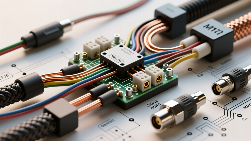
Decoding the Surveillance Camera Installation Price
When fleet managers, commercial upfitters, and automotive enthusiasts research the surveillance camera installation price, they are often met with vague, generalized estimates. However, from an automotive electrical engineering perspective, the true cost of a surveillance or multi-channel dash cam system is dictated by the vehicle's electrical architecture, the required wire gauges, connector types, and CAN-bus integration complexity. A basic OBD-II plug-and-play setup may cost a fraction of a hardwired, IP69K-rated exterior fleet surveillance system. This technical specification reference breaks down the material and labor variables that dictate installation pricing, providing the exact AWG ratings, pin configurations, and wiring topologies required for a fail-safe deployment.
Material Cost Matrix: Wire Gauges, Relays, and Connectors
The baseline material cost for a professional surveillance installation hinges on the amperage draw of the camera array and the routing distance. Voltage drop is a critical factor; undersized wiring leads to camera reboots and corrupted SD card writes. Below is the standard material specification matrix used by certified upfitters.
| Component | Specification | Application | Est. Material Cost |
|---|---|---|---|
| Primary Power Wire | 16 AWG Stranded Copper (TXL) | Main harness from battery to distribution block (Multi-cam setups >8A) | $0.45 / ft |
| Camera Drop Wire | 18 AWG Stranded Copper | Interior cabin cameras & standard dash cams (Max 5A draw) | $0.30 / ft |
| Exterior Connector | M12 X-Coded 8-Pin (IP69K) | Heavy-duty exterior PoE surveillance cameras | $18.50 / pair |
| Isolation Relay | 40A Bosch-style 5-pin (SPDT) | Preventing parasitic drain on constant 12V lines | $6.00 / unit |
| Fuse Tap | Micro2 / Micro3 Add-A-Circuit | Modern vehicle interior fuse panels (2015+ models) | $4.50 / unit |
Power Distribution & AWG Requirements
A standard single-channel dash cam requires minimal current, typically peaking at 1.5A to 2A during operation and capacitor charging. For these systems, 18 AWG wire is more than sufficient, keeping material costs low. However, commercial fleet surveillance systems utilizing 4 to 8 channels (including IR-lit interior cabins and exterior side-view cameras) can easily draw 6A to 12A continuously. According to SAE J1113 standards for electromagnetic compatibility and wiring practices, running 18 AWG wire for a 10A draw over a distance of 15 feet will result in a voltage drop exceeding 0.5V, which can trigger the low-voltage cutoff (LVC) on the camera's hardwire kit.
Hardwire Kit Pinout and LVC Thresholds
Professional installations utilize a 3-wire hardwire kit to enable parking mode surveillance. The wiring color code and termination points are strictly defined:
- Yellow Wire (Constant 12V): Connected to an always-hot fuse (e.g., interior lighting, hazard flashers). Powers the camera during parking mode.
- Red Wire (Switched 12V): Connected to an ignition-switched fuse (e.g., wipers, radio). Signals the camera to begin continuous recording and disables parking mode.
- Black Wire (Ground): Must be terminated to a bare, unpainted metal chassis bolt. Torque to 8-10 Nm to prevent ground loop noise.
Premium hardwire kits feature adjustable DIP switches for Low Voltage Cutoff (LVC). For standard 12V lead-acid batteries, the LVC should be set to 11.8V to ensure the vehicle retains enough cranking amps. For AGM batteries, a threshold of 12.0V is recommended.
Exterior Camera Routing & M12 Connector Pinouts
The most significant variable inflating the surveillance camera installation price is the integration of exterior, ruggedized cameras. Routing coaxial or Ethernet cables through the vehicle's firewall and A-pillars requires specialized grommets and fish tapes. Furthermore, exterior cameras are subjected to high-pressure washes and extreme temperatures, necessitating IP69K-rated connectors rather than standard RCA or Fakra Z connections.
Modern heavy-duty fleet setups utilize M12 X-Coded 8-pin connectors for Power over Ethernet (PoE) or high-definition AHD (Analog High Definition) signal transmission. The X-coding prevents mating errors and provides 360-degree shielding against EMI (Electromagnetic Interference) generated by the alternator.
M12 X-Coded 8-Pin Standard Pinout
| Pin Number | Signal / Power Assignment | Wire Color Code (Standard) |
|---|---|---|
| Pin 1 | Ethernet TX+ / AHD Signal | White/Orange |
| Pin 2 | Ethernet RX+ / AHD Ground | White/Green |
| Pin 3 | Ethernet TX- / Shield | Orange |
| Pin 4 | Ethernet RX- / Shield | Green |
| Pin 5 | 12V DC Power (+) | Red |
| Pin 6 | 12V DC Power (-) | Black |
| Pin 7 | Reverse Trigger Signal (12V+) | Violet |
| Pin 8 | Ignition Sense Signal | Yellow |
CAN-Bus Decoding & Reverse Trigger Integration
A common mistake in amateur installations is tapping directly into the reverse light circuit at the rear taillight assembly to trigger the backup camera overlay. In modern vehicles (2016 and newer), the Body Control Module (BCM) often uses Pulse Width Modulation (PWM) to monitor bulb health. Tapping into a PWM circuit introduces severe voltage fluctuations, resulting in a rolling 'wave' effect on the camera display or causing the DVR to crash.
To resolve this, professional upfitters install a CAN-bus decoder module. This module interfaces with the vehicle's OBD-II port or the high-speed CAN network (CAN-H / CAN-L) at the gateway module. The decoder reads the BCM's digital reverse-gear command and outputs a clean, steady 12V+ signal to Pin 7 on the camera harness. While this adds $45 to $85 to the material cost and requires specialized programming, it is mandatory for a glitch-free installation on modern multiplexed electrical systems.
Real-World Failure Modes That Inflate Repair Costs
Understanding why warranty returns happen is crucial for evaluating the true long-term cost of a surveillance system. Certified technicians adhering to ASE Electrical/Electronic Systems (A6) standards mitigate these failure modes during the initial installation:
1. Ground Loop Video Noise
Symptom: High-pitched audio whine that fluctuates with engine RPM, or horizontal scrolling bars on the video feed.
Cause: The camera ground and the DVR ground are tied to different chassis points with varying resistance, creating a ground loop.
Fix: Star-ground all surveillance components to a single, dedicated grounding bus bar. If the noise persists, install a 12V DC ground loop isolator on the power line or an AHD video isolator on the coaxial line.
2. Parasitic Drain from Ignition Sense Failure
Symptom: Dead vehicle battery after 48 hours of parking.
Cause: The hardwire kit's red (switched) wire was tapped into a fuse that remains hot during the vehicle's 'sleep' mode, or a CAN-bus module failed to enter standby.
Fix: Perform a parasitic draw test. Connect a digital multimeter in series with the negative battery terminal. Wait 45 minutes for the vehicle's modules to enter sleep mode. The draw should drop below 50mA. If it remains above 150mA, verify the fuse tap location using a factory wiring diagram and relocate the ignition sense wire to a true switched circuit, such as the windshield wiper motor fuse.
3. SD Card Corruption via Voltage Spikes
Symptom: Camera freezes upon engine cranking; files are unreadable.
Cause: Alternator load dump or cranking voltage sags corrupting the file allocation table.
Fix: Install a supercapacitor buffer or a 12V DC-DC buck converter with an integrated voltage regulator to ensure a steady 5V/2A output to the camera's micro-USB or Molex power input, isolating the DVR from the vehicle's raw 14.4V charging system spikes.
Conclusion: Value vs. Cost in Surveillance Upfits
The surveillance camera installation price is ultimately a reflection of electrical integrity. Cutting corners on AWG sizing, ignoring PWM reverse circuits, or utilizing substandard fuse taps will result in intermittent failures that far exceed the initial savings of a budget installation. By specifying 16 AWG TXL wire for main feeds, utilizing M12 X-coded connectors for exterior routing, and integrating CAN-bus decoders for trigger signals, fleet operators ensure their surveillance systems remain operational, legally compliant, and forensically reliable in the event of an incident.