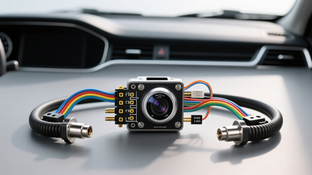
The True Reverse Camera Installation Cost: Beyond the Price Tag
When enthusiasts and daily drivers budget for aftermarket vehicle tech, they typically focus on the hardware price. However, the true reverse camera installation cost is rarely just the price of the CMOS sensor and the head unit. Hidden expenses arise from improper wiring techniques, leading to blown Body Control Modules (BCMs), fried head unit video inputs, and severe electrical faults. A $150 camera kit can quickly trigger a $1,200 dealer-level diagnostic and BCM replacement if the installer ignores modern automotive network protocols. At Autoflowwire, we analyze the intersection of automotive electrical systems and aftermarket integration to help you avoid catastrophic mistakes and ensure a safe, reliable installation.
Critical Safety Warnings Before Tapping the Harness
Before stripping a single wire, installers must recognize that modern vehicle interiors are dense networks of high-speed data buses and life-saving safety circuits. Blindly probing with a test light or multimeter can trigger irreversible damage.
Airbag Proximity and SRS Wiring
The Supplemental Restraint System (SRS) utilizes specific wiring looms, almost universally wrapped in yellow tubing or featuring yellow connector housings. These wires carry low-resistance squib circuits for airbag deployment. Never use a piercing probe (T-tap or Scotchlok) near the kick panels, B-pillars, or lower dash where SRS harnesses route to seatbelts and curtain airbags. Piercing an SRS wire can alter its resistance by a fraction of an ohm, triggering an SRS fault code or, worse, causing an inadvertent airbag deployment. Always route camera RCA and power cables at least 4 inches away from any yellow-loomed wiring.
Battery Disconnect Protocols and CAN-Bus Spikes
Modern vehicles rely on Controller Area Network (CAN-bus) systems. Disconnecting the battery while modules are awake, or back-feeding voltage into a data line during camera trigger testing, can corrupt module memory. According to MECP (Mobile Electronics Certification Professional) guidelines, you must disconnect the negative battery terminal and wait a minimum of 15 minutes before tapping into any rear lighting harness. This allows the vehicle's CAN-bus modules to enter "sleep mode," preventing voltage spikes from reaching the BCM when you reconnect power to test the reverse trigger.
Top Wiring Mistakes That Skyrocket Your Installation Cost
Mistake 1: Tapping PWM Reverse Lights Without a Filter
The most common reason a reverse camera flickers, fails to boot, or throws a "Bulb Out" code on the dash is Pulse Width Modulation (PWM). Vehicles from 2015 onward (particularly Ford, Ram, VW, and Audi) do not send a clean 12V Direct Current (DC) signal to the reverse bulbs. Instead, the BCM sends a rapid on/off pulsing signal (often around 12V to 14V, but pulsed at varying duty cycles) to monitor bulb health and extend LED life.
If you tap your camera's red trigger wire directly into a PWM circuit, the camera's internal voltage regulator will overheat from the rapid cycling, or the image will strobe violently. Furthermore, the BCM will detect the added resistance of the camera circuit, assume the reverse bulb is failing, and cut power entirely. The Fix: You must use a CAN-bus signal filter/rectifier or a 12V relay bypass to convert the PWM signal into a clean 12V DC trigger.
Mistake 2: Ground Loops and the "Alternator Whine" Fix
A ground loop occurs when the camera's ground and the head unit's ground are at slightly different electrical potentials. The RCA cable's outer metal shield, intended to block electromagnetic interference (EMI), ends up acting as a ground wire to equalize this potential difference. This creates a loop that picks up the AC ripple from the alternator, resulting in a loud, whining noise through the speakers and rolling horizontal bars on the camera display.
Amateur installers often try to fix this by buying cheap inline ground loop isolators, which degrade the video signal bandwidth and cause color loss. The proper, zero-cost fix is to ensure the camera's black ground wire is sanded down to bare, unpainted chassis metal at the rear of the vehicle, and to isolate the RCA shield at the camera end using heat shrink so it only grounds at the head unit chassis. Adhering to SAE J1113 standards for electromagnetic compatibility is crucial for clean video transmission in high-EMI vehicle environments.
Mistake 3: Undersized Wiring on Long-Wheelbase Vehicles
Most aftermarket cameras include 20 to 26 AWG zip-cord for power. While sufficient for a sedan, running 24 AWG wire over 18 feet in a Ford Transit, Chevy Express, or Dodge Ram 3500 crew cab results in severe voltage drop. Most CMOS sensors require a minimum of 11.5V to initialize. If the voltage drops below this threshold due to wire resistance, the camera will display a "No Signal" black screen when shifted into reverse, leading to hours of misdirected troubleshooting and inflated labor costs.
Technical Reference: Reverse Trigger & Power Specifications
Use this specification chart to ensure your wiring meets the electrical demands of aftermarket camera systems without overloading the vehicle's OEM harness.
| Parameter | Optimal Specification | Warning / Failure Threshold |
|---|---|---|
| Wire Gauge (Runs under 15 ft) | 18 AWG Stranded Copper | >0.5V Drop (Camera fails to boot) |
| Wire Gauge (Runs over 15 ft) | 16 AWG Stranded Copper | >1.0V Drop (Image artifacts/flicker) |
| Camera Trigger Current Draw | 150mA - 250mA | >500mA (Requires dedicated relay) |
| Inline Fuse Rating (Power) | 2A Mini (ATM) Blade | Never exceed 5A (Fire risk) |
| RCA Shield Grounding | Head Unit Chassis Only | Grounded at both ends (Alternator whine) |
The Safe Trigger Wire Integration Protocol (Relay Bypass)
To completely eliminate the risk of BCM damage and bypass PWM issues, professional installers use a standard Bosch-style 30A Mini ISO relay. This ensures the camera draws zero current from the vehicle's delicate reverse light circuit. Refer to Bosch Automotive Relays documentation for standard pinout configurations.
- Pin 85 (Coil Ground): Connect to a clean, unpainted chassis ground near the taillight.
- Pin 86 (Coil Trigger): Tap into the OEM reverse light wire. Because the relay coil draws only ~150mA, it will not trigger a BCM "bulb out" fault, even on a PWM circuit. The relay will simply click rapidly, but the output will remain stable.
- Pin 30 (Common / Input): Connect to a clean 12V constant or ignition-switched 12V source (fused at 2A).
- Pin 87 (Normally Open / Output): Connect to the red trigger wire of the aftermarket camera and the RCA trigger pigtail running to the head unit.
By utilizing this relay diagram, the reverse light circuit only acts as a low-current switch. The actual power required to wake the camera and trigger the head unit's video input is sourced directly from a robust 12V battery or fuse box line, entirely isolating the vehicle's CAN-bus and lighting modules from aftermarket interference.
Conclusion: Protecting Your Investment
Minimizing your reverse camera installation cost isn't about buying cheaper wire or skipping steps; it's about doing the job correctly the first time to avoid catastrophic electrical failures. By respecting SRS safety zones, testing for PWM signals, eliminating ground loops at the source, and utilizing relay bypasses for trigger wires, you ensure that your backup camera system is as reliable and safe as the OEM equipment it supplements. Always verify your specific vehicle's wiring schematic via a factory service manual before making any hardwired connections.