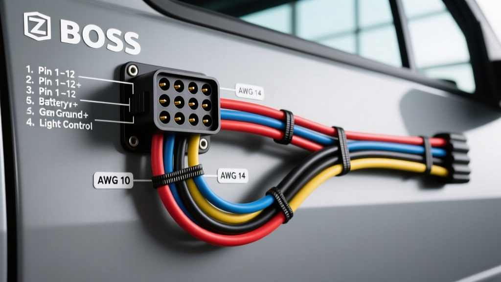
Boss Truck-Side Harness Architecture Overview
When installing, maintaining, or diagnosing a Boss snow plow system, understanding the truck-side wiring harness is critical. Modern Boss plows utilize the Multiplex System Controller (MSC) architecture, which replaces legacy relay-based systems with solid-state switching and CAN-bus data communication. The truck-side harness acts as the central nervous system, bridging the vehicle's OEM lighting and power circuits to the 13-pin front-mounted connector. This technical specification reference details the exact pinout configurations, wire gauge requirements, and routing protocols necessary to ensure reliable operation in extreme sub-zero environments.
13-Pin Connector Pinout Specifications
The interface between the truck and the plow is a heavy-duty, weather-sealed 13-pin circular connector. Unlike older 11-pin setups, the 13-pin configuration accommodates both high-current lighting feeds and low-voltage multiplex data signals. Below is the definitive pinout reference for the Boss truck-side 13-pin receptacle.
| Pin | Wire Color | Function / Circuit | AWG (SAE J1128 GXL) | Signal Type |
|---|---|---|---|---|
| 1 | White | Chassis Ground (Lighting) | 12 AWG | Ground Return |
| 2 | Brown | Tail / Marker / Clearance | 14 AWG | 12V DC (+) |
| 3 | Green | Left Turn / Stop Lamp | 14 AWG | 12V DC (+) |
| 4 | Yellow | Right Turn / Stop Lamp | 14 AWG | 12V DC (+) |
| 5 | Blue | High Beam Headlamp | 14 AWG | 12V DC (+) |
| 6 | Black | Low Beam Headlamp | 14 AWG | 12V DC (+) |
| 7 | Red | Main Plow Battery Feed | 10 AWG (Plug) / 2 AWG (Run) | 12V DC (+) High Current |
| 8 | Black w/ White Tracer | Heavy Ground (Hydraulic/MSC) | 10 AWG (Plug) / 2 AWG (Run) | High Current Ground |
| 9 | Orange | Ignition Sense / Accessory | 16 AWG | 12V DC (+) Switched |
| 10 | Purple | Multiplex Data (CAN High) | 18 AWG Shielded | Digital Data |
| 11 | Light Green | Auxiliary / Work Lights | 14 AWG | 12V DC (+) |
| 12 | Pink | Controller Power Feed | 16 AWG | 12V DC (+) |
| 13 | Bare / Drain | Data Shield Ground | 18 AWG | Shield Drain |
Note: Wire colors may vary slightly on older DXT or XT relay-based harnesses. Always verify with a multimeter against the vehicle's OEM BCM (Body Control Module) outputs before splicing.
Heavy Gauge Power and Ground Routing Requirements
The most common failure point in any snow plow electrical system is inadequate power delivery or poor grounding. The Boss MSC system requires precise heavy-gauge routing to handle the inductive spike and current draw of the hydraulic pump motor, which can exceed 120 amps during startup under heavy load.
Main Power Feed (Pin 7)
- Wire Gauge: 2 AWG copper, rated for low-temperature flexibility (SAE J1128 or equivalent welding cable).
- Routing: Must be routed from the vehicle battery positive terminal to the MSC power stud or main solenoid. Avoid sharp bends and exhaust manifolds.
- Overcurrent Protection: A 150A Mega or MIDI fuse must be installed within 18 inches of the battery positive terminal. This complies with SAE J1128 and ABYC marine/automotive standards for battery-adjacent short-circuit protection.
- Termination: Use closed-end, adhesive-lined heat-shrink ring terminals. Torque the battery terminal to 10-12 ft-lbs and the MSC stud to 8-10 ft-lbs.
Heavy Ground Return (Pin 8)
- Wire Gauge: 2 AWG copper.
- Termination Point: Do NOT ground to the vehicle body or sheet metal. The heavy ground must terminate directly to the engine block or the OEM negative battery ground stud on the chassis frame.
- Surface Prep: Remove all paint, powder coating, and rust using a wire wheel or sanding disc. Apply a star washer between the lug and the bare metal surface to ensure vibration-resistant contact. Coat the finished connection with battery terminal protector spray to prevent galvanic corrosion from road salt.
Multiplex System Controller (MSC) Integration
The MSC module is typically mounted inside the cab, under the dashboard on the driver's side. It processes the low-current multiplex signals from the in-cab controller and switches the high-current outputs to the plow. Wiring the MSC into the truck's OEM harness requires tapping into the vehicle's lighting circuits.
Headlamp and Turn Signal Interfacing
Modern trucks utilize CAN-bus or LIN-bus lighting systems controlled by the BCM. Splicing directly into OEM headlamp wires can trigger dashboard error codes or cause the BCM to shut down the lighting circuit due to perceived short circuits. To interface the Boss truck-side harness with modern OEM lighting:
- Use PWM-Compatible Relays or Isolators: If the vehicle uses Pulse Width Modulation (PWM) for daytime running lights (DRL) or headlamps, install a Boss-approved PWM filter or interface module to convert the signal to a clean 12V DC output for Pins 5 and 6.
- T-Tap Prohibition: Never use piercing T-taps for lighting circuits. They allow moisture ingress and cause voltage drop. Always use solder-seal splice connectors (e.g., Raychem SolderSleeve) or OEM-style add-a-circuit fuse taps at the BCM connector.
- Ignition Sense (Pin 9): This wire must be connected to a true ignition-switched 12V source. If connected to a constant 12V source, the MSC will not power down, leading to parasitic battery drain. If connected to an accessory circuit that powers down too early, the plow may drop unexpectedly when shifting out of gear.
Weatherproofing and Cold-Weather Loom Specifications
Snow plow wiring operates in highly corrosive, high-vibration, and sub-zero environments. Standard corrugated plastic split-loom becomes brittle and cracks at temperatures below 0°F (-17°C), exposing the harness to calcium chloride and magnesium chloride brines.
- Outer Jacketing: The truck-side harness should be wrapped in a woven nylon braided sleeving or a TCA (Thermoplastic Copolyester) flexible conduit. These materials remain pliable at -40°F.
- Connector Sealing: Apply a heavy coat of dielectric silicone grease (e.g., Nyogel 760G or standard marine grease) to the 13-pin connector pins. This prevents micro-arcing and moisture-induced galvanic corrosion.
- Drip Loops: When routing the harness through the firewall or near the grille, always create a 'drip loop'—a U-shaped bend in the wire that forces water to drip off the lowest point rather than running down the wire directly into the connector or MSC module.
Diagnostic Troubleshooting: Truck-Side Failure Modes
When diagnosing electrical faults, isolate the truck-side harness from the plow-side harness using a multimeter. Refer to FMVSS 108 standards for lighting voltage requirements. Below is a decision tree for common truck-side harness failures:
Symptom: Plow Lights Flicker or Dim When Hydraulic Pump Engages
- Cause: Excessive voltage drop on the heavy ground (Pin 8) or main power (Pin 7) circuits.
- Test: Set multimeter to DC Volts. Place red probe on battery positive and black probe on Pin 7 at the truck connector. Engage plow. Voltage drop must be less than 0.5V. Repeat for ground (Battery negative to Pin 8). Drop must be less than 0.2V.
- Fix: Clean ground stud, replace corroded Mega fuse, or upgrade to 1/0 AWG cable if the run exceeds 10 feet.
Symptom: Plow Drops or Drifts Down When Truck is Turned Off
- Cause: The MSC module is not receiving the 'ignition off' signal, keeping the hydraulic valves energized or failing to engage the internal drop-lock solenoid.
- Test: Probe Pin 9 (Orange - Ignition Sense) at the truck connector. It should read 0V when the key is removed. If it reads 12V, it is wired to a constant or delayed-accessory circuit.
- Fix: Re-route the Orange wire to a strict ignition-run circuit at the OEM fuse panel.
Symptom: In-Cab Controller Displays 'No Communication' Error
- Cause: CAN-bus data line failure between the controller, the MSC, and the 13-pin connector (Pin 10 / Pin 13).
- Test: Check continuity on the Purple data wire from the MSC to the 13-pin plug. Inspect for crushed wires under the dash or near the hood latch where the harness passes through the grille.
- Fix: Repair broken shielded wire using solder and heat shrink. Ensure the bare drain wire (Pin 13) is grounded only at the MSC module end to prevent ground loops that corrupt data signals.
For comprehensive wiring schematics and vehicle-specific MSC mounting locations, technicians should always consult the latest Boss Snowplows Technical Service Bulletins and installation guides tailored to the specific truck make, model, and OEM lighting package.