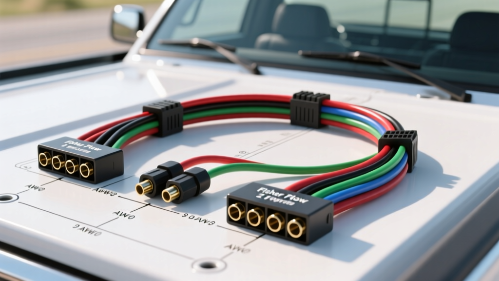
Anatomy of the Fisher 2-Plug Electrical System
The Fisher 2-plug electrical system is a legacy workhorse in the snow removal industry, commonly found on older Minute Mount and early Minute Mount 2 setups. Unlike modern multiplexed 3-plug or 4-plug systems, the 2-plug architecture separates the heavy amperage hydraulic power from the low-amperage control signals. The system utilizes a robust 2-pin power connector (handling the hydraulic motor solenoid circuit) and a 9-pin control connector (managing directional solenoids, ignition sense, and lighting). While reliable, the factory Fisher plow 2 plug wiring harness was designed for standard-wheelbase, regular-cab trucks of the late 1990s and early 2000s.
Why Upgrade the Factory 2-Plug Harness?
When adapting an older Fisher plow to a modern crew-cab or long-bed truck (such as a 2015+ Ram 3500 or Ford F-350 with an 8-foot bed), the factory harness length and wire gauge become critical failure points. The primary issue is voltage drop. The hydraulic motor solenoid requires a minimum of 10.5 volts under load to actuate reliably. If you stretch the factory 10 AWG power wires over an additional 6 to 8 feet of frame rail, resistance increases exponentially. This results in a sluggish plow, delayed solenoid engagement, and premature burnout of the hydraulic motor contacts due to arcing.
This upgrade and modification project focuses on extending the harness while simultaneously up-gauging the power circuit and replacing degraded OEM PVC insulation with modern cross-linked polyethylene (XLPE) automotive wire.
Fisher 9-Pin Control Plug Pinout & Wire Colors
Before cutting or splicing, it is imperative to map the 9-pin control connector. Fisher's color codes have seen minor variations over the decades depending on the specific joystick controller (e.g., EZ-V vs. straight blade), but the standard 9-pin layout remains consistent for the core hydraulic functions. Always verify against your specific truck-side isolation module.
| Pin | Function | Standard OEM Wire Color | Upgrade Wire Spec |
|---|---|---|---|
| A | Ignition / Controller Power | Red | 14 AWG GXL |
| B | System Ground | Black | 14 AWG GXL |
| C | Motor Solenoid Trigger | White | 16 AWG TXL |
| D | Raise Solenoid | Brown | 16 AWG TXL |
| E | Lower Solenoid | Black w/ White Tracer | 16 AWG TXL |
| F | Right Angle Solenoid | Green | 16 AWG TXL |
| G | Left Angle Solenoid | Orange | 16 AWG TXL |
| H | Lighting / Park Sense | Purple | 16 AWG TXL |
| J | Float / Diagnostic | Yellow | 16 AWG TXL |
Project Guide: Heavy-Duty Harness Extension & Upgrade
This modification requires basic automotive electrical fabrication skills. You will be replacing the truck-side harness routing from the battery/solenoid location to the front bumper receiver area.
Phase 1: Wire Selection & Gauge Upgrades
The most critical step in this upgrade is abandoning standard PVC primary wire. PVC becomes brittle in sub-zero temperatures and degrades when exposed to road salt and calcium chloride. Instead, source SAE J1128 compliant GXL or TXL wire. GXL features a thicker insulation wall, making it ideal for the 2-pin power circuit where abrasion against the frame rail is a concern.
- 2-Pin Power Circuit (Motor Solenoid): Upgrade from the factory 10 AWG to 6 AWG stranded bare copper GXL wire. This drastically reduces resistance over long wheelbase runs. Use Red for Battery Positive and Black for Chassis Ground.
- 9-Pin Control Circuit: Use 16 AWG TXL (thin-wall cross-linked) wire. TXL is highly flexible, which is crucial for the control harness that must flex when the plow turns left and right.
- Conduit: Encase the entire extended run in split-loom tubing wrapped with Tesa 51036 PET fleece tape to prevent chafing and resist salt intrusion.
Phase 2: Splicing & Environmental Sealing
Do not use standard crimp connectors or electrical tape for under-hood plow wiring. The thermal cycling and high-pressure wash environments will destroy them within a single season.
- Prepare the Wires: Strip the GXL/TXL wire using a precision thermal stripper or a calibrated wire stripper to avoid nicking the copper strands. Nicked strands create localized resistance and heat.
- Solder-Seal Splicing: For the 16 AWG control wires, use dual-wall, adhesive-lined heat shrink solder sleeves. The inner ring melts and solders the connection, while the outer wall shrinks and the inner adhesive seals out moisture. This creates a completely waterproof, strain-relieved joint.
- High-Current Crimping: For the 6 AWG power extension, use a closed-barrel copper splice crimp with an adhesive-lined 3/8-inch heat shrink outer shell. Crimp using a heavy-duty hex-crimp tool to ensure a gas-tight mechanical bond.
- Dielectric Grease Application: Apply a generous amount of silicone-based dielectric grease to the 9-pin and 2-pin connector cavities. This prevents galvanic corrosion between the brass pins and the harsh winter environment.
Phase 3: Routing Through the Firewall & Chassis
When routing the upgraded Fisher plow 2 plug wiring harness along the frame rail, maintain a minimum clearance of 6 inches from the exhaust manifold and turbocharger piping. Secure the harness every 12 inches using UV-resistant, stainless-steel cushion clamps (P-clips) lined with EPDM rubber. Never use standard nylon zip-ties directly on the wire bundle, as the sharp edges will eventually cut through the GXL insulation due to engine vibration.
Where the harness passes through the firewall to reach the in-cab controller, use a dedicated rubber grommet. Pierce the grommet with a small awl, lubricate the wire bundle with soapy water, and pull it through. Once seated, inject expanding polyurethane foam or silicone sealant into the grommet cavity to block carbon monoxide and moisture from entering the cab.
Voltage Drop Troubleshooting Matrix
If you have completed the upgrade but are still experiencing sluggish hydraulic performance or unresponsive solenoids, use this diagnostic matrix to isolate the fault. You will need a digital multimeter (DMM) capable of measuring DC voltage and a helper to operate the joystick.
| Symptom | Probable Cause | Diagnostic Test & Fix |
|---|---|---|
| Plow raises slowly, motor sounds labored | Voltage drop on 2-pin Power Positive | Measure voltage at battery vs. solenoid stud under load. If drop > 0.5V, check for loose battery lugs or corroded 2-pin plug pins. |
| Motor solenoid clicks rapidly but won't engage | High resistance on Control Pin C (White) | Check continuity on Pin C. A reading > 2 ohms indicates a bad splice. Re-solder using adhesive-lined sleeves. |
| Plow drifts down slowly when raised | Leaking O-ring or Pin E (Lower) short | Verify Pin E has 0V when not pressing 'Down'. If voltage is present, trace harness for pinched 16 AWG wire shorting to ground. |
| Controller displays 'No Plow Connected' | Open circuit on Pin A (Ign) or Pin B (Gnd) | Test 12V at truck-side plug Pin A with key on. If missing, check inline 10A fuse and firewall grommet routing. |
Torque Specifications & Final Assembly
When terminating the 6 AWG power wires at the hydraulic motor solenoid, use heavy-duty 1/4-inch ring terminals. The solenoid studs are typically 1/4-20 thread. Torque the terminal nuts to exactly 120 in-lbs (10 ft-lbs). Under-torquing leads to arcing and melted plastic solenoid housings, while over-torquing can strip the brass stud or crack the internal ceramic contactor block. Apply a post-assembly coating of fluid film or lithium-based grease over the terminal to prevent calcium chloride corrosion.
References & Standards
- SAE International - J1128: Low Tension Primary Cable (Guidelines for GXL/TXL wire insulation and thermal ratings in automotive applications).
- Fisher Engineering - Installation & Maintenance Manuals (Reference for legacy 2-plug Minute Mount electrical schematics and solenoid torque specs).
- TE Connectivity - Automotive Sensor and Interconnect Standards (Best practices for environmental sealing and dual-wall heat shrink application in high-vibration zones).