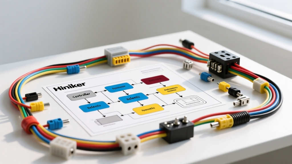
Mastering the Hiniker Plow Wiring Diagram Architecture
When a Hiniker snow plow system—whether a Scoop, V-Blade, or C-Blade—fails in the middle of a storm, blind part swapping is a costly and dangerous mistake. Proper diagnostics require a systematic approach guided by the official Hiniker plow wiring diagram. Unlike older, purely mechanical relay systems, modern Hiniker setups utilize advanced multiplexing or high-amperage isolation solenoids paired with precision hydraulic valve coils. This step-by-step troubleshooting flow is designed for automotive electrical technicians and advanced DIYers to isolate faults from the battery terminal to the hydraulic manifold, ensuring maximum uptime during the winter season.
Phase 1: Main Power and Motor Ground Isolation
The most common failure point in any snow plow electrical system is not the cab controller, but the high-amperage power delivery network. The Hiniker hydraulic motor requires massive current spikes, often exceeding 250 amps during startup and heavy load conditions. According to the SAE J1128 standards for low tension primary cable, wire gauge must be matched to both amperage and physical length to prevent catastrophic voltage drop and insulation melting.
Testing the Isolation Solenoid
Hiniker systems typically use a heavy-duty intermittent-duty solenoid rated for a 500A surge, mounted in the engine bay to isolate the plow motor from the truck's main electrical system when not in use.
- Verify 12V+ at the large input terminal. This is usually fed by a 1 AWG or 2 AWG red welding cable directly from the alternator/battery junction block.
- Check the small trigger wire, typically a 10 AWG red or white wire. When the controller commands the plow to raise, this pin should receive 12V+. If missing, the fault is upstream in the cab harness or controller.
- Perform a voltage drop test across the solenoid's large terminals under load. A reading above 0.2V indicates internal contact pitting and requires immediate solenoid replacement.
Snow plow prep packages typically require a minimum 140A to 160A alternator. If your truck is equipped with a standard 105A alternator, the hydraulic motor will drain the battery faster than the alternator can replenish it, leading to voltage starvation at the solenoid trigger circuit and erratic controller behavior.
Motor Ground Strap Verification
The hydraulic motor grounds through a braided copper strap to the truck chassis. Never rely on the motor mounting bolts for the primary ground path. Remove the ground bolt, clean the chassis surface to bare metal using a wire wheel, apply a thin layer of dielectric grease to the perimeter to prevent moisture ingress, and torque the hardware to 25 lb-ft using a star washer. Use a digital multimeter to verify continuity from the motor casing to the negative battery terminal; resistance must be strictly less than 0.05 ohms.
Phase 2: Cab Controller and 12-Pin Harness Routing
Standard and legacy Hiniker systems rely on a robust 12-pin weatherpack connector to bridge the cab controller and the under-hood relay network. Corrosion, pin push-back, and broken retaining clips are notorious failure points here. Referencing the Hiniker plow wiring diagram, use a terminal pin extraction tool to inspect the following critical circuits:
| Pin | Wire Color | Function | Diagnostic Target |
|---|---|---|---|
| 1 | Red | Ignition 12V+ Feed | Check for 12V+ with key ON. Loss of power here kills the controller. |
| 2 | Black | Main Controller Ground | Must read less than 0.1 ohms to battery negative. High resistance causes erratic LCD displays. |
| 3 | Blue | Raise Valve Trigger | 12V+ output when raise button is pressed. Drives the raise relay coil. |
| 4 | White | Lower Valve Trigger | 12V+ output for gravity drop valve coil. |
| 5 | Green | Left Angle Trigger | 12V+ output for left angle directional valve. |
| 6 | Yellow | Right Angle Trigger | 12V+ output for right angle directional valve. |
Always apply a high-quality silicone dielectric compound, such as Nyogel 760G, to these pins before mating. Standard white lithium grease will wash out in wet conditions and trap moisture, leading to galvanic corrosion between the copper and brass terminals.
Phase 3: Hydraulic Solenoid Valve Coil Testing
If the controller sends the trigger signal but the plow does not move, the fault lies at the hydraulic manifold valve coils. Hiniker hydraulic manifolds, particularly the D-series and older C-series blocks, utilize cartridge-style solenoid valves. These valves are actuated by 12V DC electromagnetic coils. Over time, the intense heat generated by the hydraulic fluid, which can easily exceed 140°F during continuous plowing, degrades the enamel insulation on the coil windings.
Disconnect the coil and set your digital multimeter to the Ohms setting. A healthy 12V Hiniker valve coil should read between 4.5 and 6.5 ohms.
- Open Loop (OL): The internal copper windings have burned out or the internal thermal fuse has blown. Replace the coil.
- Below 2.0 Ohms: The coil is shorted internally. This will blow the cab harness inline fuse or permanently damage the controller's internal MOSFET drivers.
- Magnet Test: With the coil energized, a small screwdriver should be strongly attracted to the top nut of the valve stem. If there is no magnetic pull despite 12V being present, the coil is dead.
Phase 4: Lighting and Headlamp Harness Integration
Headlamp integration is where the Hiniker plow wiring diagram intersects with the vehicle's OEM CAN-bus or multiplex lighting system. Most modern Hiniker plows use HB3/HB4 or H11 connectors. HB3 (9005) and HB4 (9006) bulbs utilize a 3-pin connector where Pin 1 is Ground, Pin 2 is Low Beam, and Pin 3 is High Beam. Cross-wiring these during aftermarket adapter installation will result in immediate backfeed.
Modern trucks utilizing CAN-bus multiplex lighting systems monitor the current draw of the headlamp circuits. When you plug in a traditional Hiniker snow plow harness, the truck's Body Control Module (BCM) detects an abnormal resistance or current spike and shuts down the lighting circuit to protect the wiring. To bypass this, the Hiniker plow wiring diagram dictates the installation of a dedicated isolation module and relay harness. This module draws power directly from the battery to feed the plow lamps, while using the truck's OEM headlamp signals purely as low-amperage triggers.
Symptom-Cause-Fix Decision Tree
Use this rapid-reference diagnostic tree to pinpoint issues without guessing:
- Symptom: Controller screen is completely dead.
Cause: Blown inline fuse on Pin 1 (Red) or open circuit on Pin 2 (Black).
Fix: Probe the vehicle-side 12-pin connector with a test light. If power is present, replace the controller. If absent, trace the firewall pass-through grommet for severed wires. - Symptom: Plow angles left but will not angle right.
Cause: Broken yellow trigger wire (Pin 6) in the cab harness, or a seized right-angle spool valve.
Fix: Unplug the 12-pin connector and probe the vehicle-side Pin 6 with a multimeter while pressing the right-angle button. If 12V+ is present, the electrical system is intact, and the fault is a mechanical binding in the hydraulic manifold or a failed right-angle coil. - Symptom: Plow drops slowly when driving over bumps.
Cause: Debris trapped in the lower valve seat or a failing lower coil diode.
Fix: Swap the lower coil with the angle coil. If the problem moves, replace the coil. If it stays, rebuild the hydraulic valve cartridge. - Symptom: Motor runs continuously but plow does not raise.
Cause: Pump coupling failure or severe hydraulic fluid bypass.
Fix: This is a mechanical failure. Inspect the motor shaft coupling and check fluid levels using AW-32 hydraulic fluid.
Final Verification and Preventative Maintenance
Once the fault is rectified, perform a full cycle test. Operate the plow through all functions a minimum of ten times while monitoring the voltage at the battery. According to Hiniker's official service guidelines, the voltage should not dip below 10.5V during motor operation. If it does, the truck's alternator and battery group size must be evaluated for snow plow prep package compliance. Proper adherence to the Hiniker plow wiring diagram and rigorous voltage drop testing will ensure your equipment survives the harshest winter conditions.